Upside adding water type humidifier with water tank and base separable

A technology of adding water type and humidifier, applied in the direction of heating method, air humidification system, lighting and heating equipment, etc., can solve the problems of submerged fan, damage to fan's auxiliary circuit, complicated mold and injection molding process, etc., to avoid mutual interference, The injection molding process is simple and the effect of convenient water addition operation

Active Publication Date: 2017-12-01
FOSHAN JINXINGHUI ELECTRICAL APPLIANCE
View PDF16 Cites 2 Cited by
  • Summary
  • Abstract
  • Description
  • Claims
  • Application Information

AI Technical Summary

Problems solved by technology

[0004] The water tank of the top-filling humidifier is erected above the base, and the water tank and the base are often realized by one-time injection molding, but because the water tank and the base also need to be injection-molded to form functional parts such as mist outlet channels, air ducts, water tanks, and water outlets Or the installation structure will often lead to very complicated mold and injection molding process, and the production cost will increase significantly; in addition, the opening or closing of the water tank valve makes the water in the water tank flow into the water tank in a controlled manner. There are foreign objects such as hair, once the foreign object is stuck in the water level control device, it will cause the water level control device to fail, and the water in the water tank will continue to flow to the sink
However, the air outlet of the fan of the traditional humidifier is set beside the water tank, and the position is low. When the water level of the water tank rises to a certain height, it will submerge the air outlet of the fan, and the water will flow back into the fan, causing the fan to be damaged. Its auxiliary circuit is damaged

Method used


Image

  • Upside adding water type humidifier with water tank and base separable
  • Upside adding water type humidifier with water tank and base separable
  • Upside adding water type humidifier with water tank and base separable

Examples


Embodiment 1

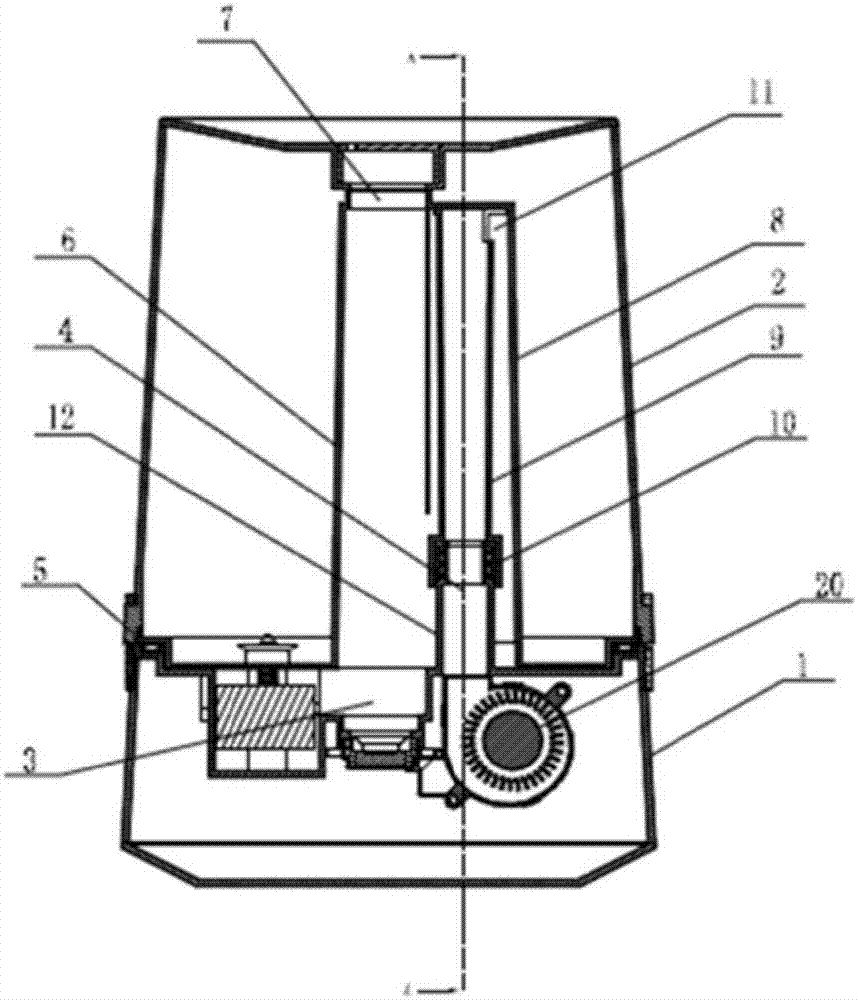
[0042] see figure 1 , 2 , the upper water type humidifier of this embodiment includes a base 1 and a water tank 2 with a water inlet on the top surface; a water tank 3 is provided on the top surface of the base 1, and the water tank 3 is provided with an ultrasonic atomization device; a fan 20 is installed in the base 1 , the air outlet 4 of the fan is upwardly exposed on the base 1; the bottom of the water tank 2 is provided with a water outlet; The water is controlled to flow into the water tank 3, and the water discharge valve can be a solenoid valve, a rubber cover with a magnetic rod or a rubber cover with a ejector rod, etc., which can be opened or closed by receiving electromagnetic signals or mechanical touch; installed in the water tank 3 There is a water level control device for generating electrical signals or magnetic signals or mechanical actions to control the opening or closing of the water valve according to the water level in the water tank 3. The water level...

Embodiment 2

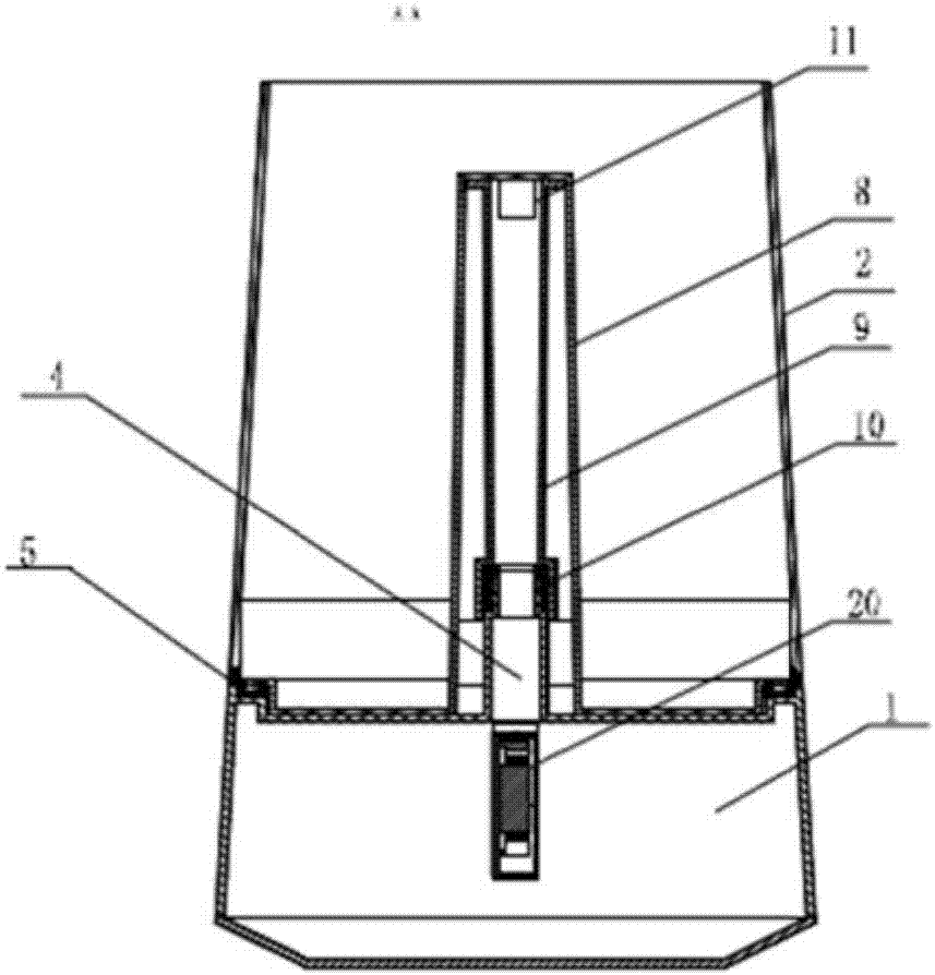
[0048] see image 3 , 4 , the upper water type humidifier of this embodiment includes a base 1 and a water tank 2 with a water inlet on the top surface; a water tank 3 is provided on the top surface of the base 1, and the water tank 3 is provided with an ultrasonic atomization device; a fan is installed in the base 1, The air outlet 4 of the fan is tubular and exposed upward on the base 1; the bottom of the water tank 2 is provided with a drain; The edge of the top surface of the base 1 is provided with a sealing ring 5, and the water tank 2 is placed on the base 1, so that the water tank 2 and the base 1 are detachably sealed. The base 1 and the water tank 2 are provided with buckles that cooperate with each other. After the water tank 2 is placed on the base 1, the buckles are fastened to ensure that the connection between the water tank 2 and the base 1 is stable and well sealed.

[0049] The water tank 2 is made of plastic, and a mist outlet channel is integrally formed ...

Embodiment 3

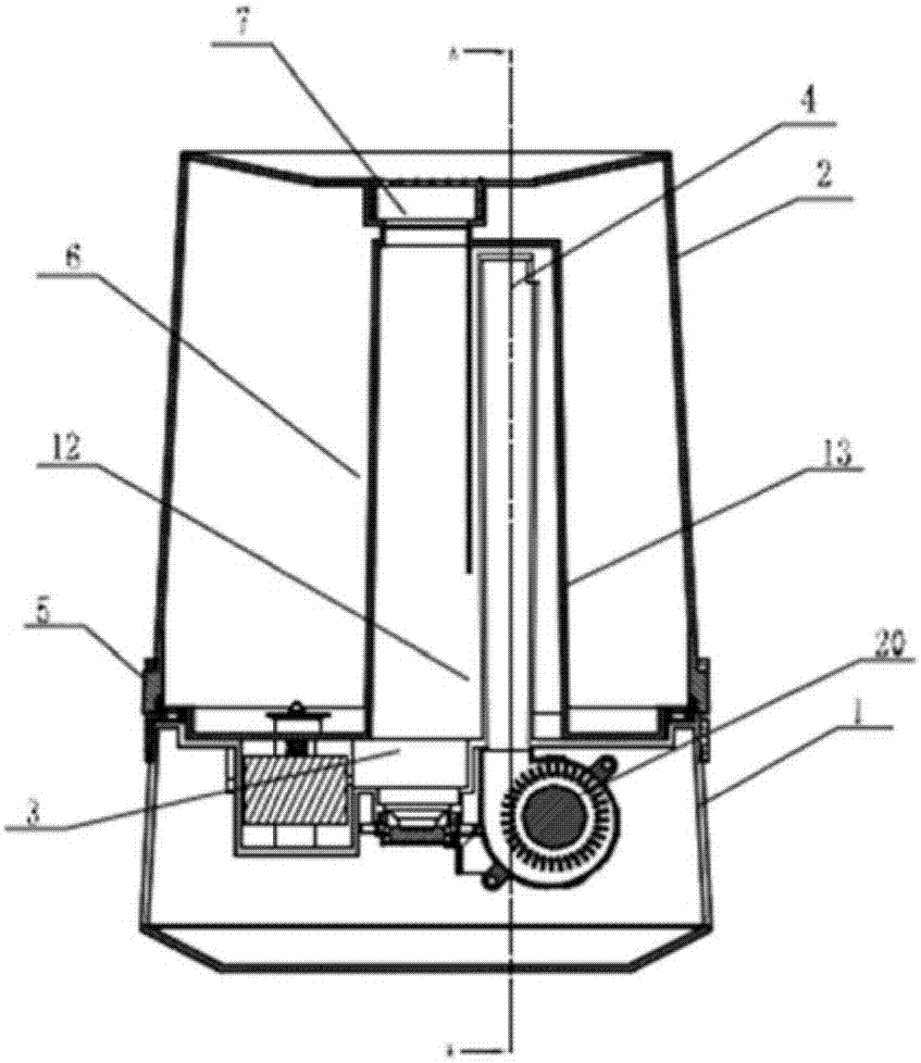
[0053] see Figure 5 , 6 , the upper water type humidifier of this embodiment includes a base 1 and a water tank 2 with a water inlet on the top surface; a water tank 3 is provided on the top surface of the base 1, and the water tank 3 is provided with an ultrasonic atomization device; a fan 20 is installed in the base 1 , the air outlet 4 of the fan is exposed upward on the base 1; the bottom of the water tank 2 is provided with a water outlet; the water outlet is installed with a water valve, and the water tank 3 is installed with a water level for controlling the opening or closing of the water valve according to the water level in the water tank 3. Control device; the edge of the top surface of the base 1 is provided with a sealing ring 5, and the water tank 2 is placed on the base 1, so that the water tank 2 and the base 1 are detachably sealed. The base 1 and the water tank 2 are provided with buckles that cooperate with each other. After the water tank 2 is placed on t...


PUM


Abstract

The invention provides an upside adding water type humidifier with a water tank and a base separable and high safety. The humidifier comprises the base, the water tank and a fan; the top of the base is provided with a water channel which is provided with an atomization device; an air outlet of the fan is connected to a fog outlet channel through an air pipe; the upper part of the water tank is provided with a water inlet, and the water tank is provided with a drain hole which is provided with a drain valve; a water level control device is arranged and used for controlling the opening or closure of the drain valve according to the water level in the water channel; and the water tank is removably connected to the base, and an air outlet of the fan or at least one part of the horizontal section of the air pipe is located within the height range between 50%-98% of the maximum water capacity of the water tank. According to the upside adding water type humidifier provided by the invention, the connection mode of an air duct structure and the water tank with the base is improved, so the humidifier facilitates of adding water; moreover, even if the water level control device is failed, the water in the water tank can not enter the fan or flow out of the humidifier, so the using safety is ensured.

Description

technical field [0001] The present invention relates to a humidifier. Background technique [0002] With the improvement of living conditions, people have higher and higher requirements for the comfort of the living environment. Air humidity is one of the important factors affecting comfort, especially in northern areas and places where air conditioners are used for a long time, the air is relatively dry, so humidification Appliances are increasingly becoming a must-have for many households. [0003] At present, most of the humidifiers on the market are humidifiers with a separate water tank, and the water filling port is arranged at the bottom of the water tank. When adding water to this type of down-filling humidifier, the user is required to lift the water tank through the handle first, then turn the water tank over so that the bottom of the water tank faces upwards, and then open the water-filling cover used for sealing at the bottom of the water tank, and fill up the w...

Claims


Application Information

Patent Timeline
IPC IPC(8): F24F6/12F24F11/02
CPCF24F6/12
Inventor 蔡镜波
Owner FOSHAN JINXINGHUI ELECTRICAL APPLIANCE
Why Eureka
Try Eureka