
Vapor chamber structure and manufacturing method thereof

A technology of vapor chamber and support structure, which can be applied to structural parts of electrical equipment, cooling/ventilation/heating renovation, electrical components, etc.

Inactive Publication Date: 2017-12-01
陈翠敏
View PDF9 Cites 7 Cited by
  • Summary
  • Abstract
  • Description
  • Claims
  • Application Information

AI Technical Summary

Problems solved by technology

[0008] In view of the problems in the prior art that the vapor chamber cannot be reduced in weight and the heat dissipation efficiency is not good, the present invention discloses a vapor chamber structure and its manufacturing method, wherein:

Method used


Image

  • Vapor chamber structure and manufacturing method thereof
  • Vapor chamber structure and manufacturing method thereof
  • Vapor chamber structure and manufacturing method thereof

Examples


Embodiment Construction

[0049] Since the present invention discloses a uniform temperature plate structure, the heat conduction principle used therein has been understood by those with ordinary knowledge in the relevant technical field, so the following description will not be fully described. At the same time, the figures to be compared in the following text express schematic diagrams related to the characteristics of the present invention, and are not drawn completely according to the actual situation and are described first.

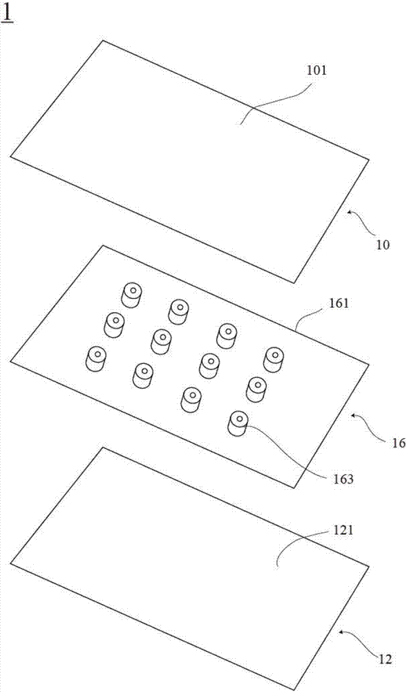
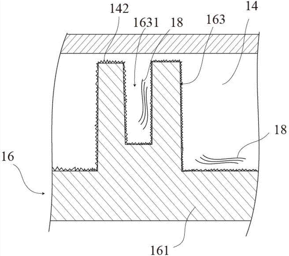
[0050] Please also refer to figure 1 and figure 2 , Are the three-dimensional exploded schematic diagram of the temperature uniform plate structure proposed by the present invention and the three-dimensional cross-sectional schematic diagram of an embodiment. The uniform temperature plate structure 1 includes a first plate 10, a second plate 12, a cavity 14 space, a supporting structure 16 and a working fluid 18. The first plate body 10 has a first surface 101 and an opposite ...


PUM


Abstract

The invention relates to a vapor chamber structure which comprises a first plate body, a second plate body, a cavity, a supporting structure and working fluid. The first plate has a first surface and a second surface; the second plate body has a third surface and a fourth surface; the cavity is defined when the first plate body and the second plate body are correspondingly covered, and a capillary structure is arranged in the cavity and attached to the inner wall; the supporting structure exists in the cavity and is used for supporting the first plate body and the second plate; the working fluid is sealed in the cavity; and the supporting structure is composed of a third plate body and a protruding column, the protruding column is arranged on the third plate body and is further provided with a sinking part, and the vapor chamber structure can achieve the effect of being light through the supporting structure.

Description

【Technical Field】 [0001] The invention relates to a uniform temperature plate structure and a manufacturing method thereof, in particular to a more lightweight uniform temperature plate structure and a manufacturing method thereof. 【Background technique】 [0002] Heat pipes have an apparent thermal conductivity that is several to several tens of times that of metals such as copper and aluminum, which is quite excellent. Therefore, they are used as cooling components for various devices related to thermal countermeasures. In terms of shape, heat pipes can be divided into round pipe-shaped heat pipes and flat-shaped heat pipes. In order to cool the parts to be cooled of electronic equipment such as CPUs, it is preferable to use a flat heat pipe or a uniform temperature plate for heat dissipation from the viewpoint that it is easy to install on the parts to be cooled and a wide contact area can be obtained. With the miniaturization and space saving of cooling mechanisms, and the li...

Claims


Application Information

Patent Timeline
IPC IPC(8): F28D15/02F28D15/04H05K7/20
CPCF28D15/0283F28D15/04H05K7/20936
Inventor 陈翠敏
Owner 陈翠敏
Learn More