

Binocular vision splicing method based on laser tracker
A technology of laser tracker and binocular vision, applied to instruments, optical devices, measuring devices, etc., can solve the problems of time-consuming algorithms and low efficiency
Active Publication Date: 2017-12-01
DALIAN UNIV OF TECH
View PDF6 Cites 34 Cited by
- Summary
- Abstract
- Description
- Claims
- Application Information
AI Technical Summary
Problems solved by technology
This invention can automatically and conveniently carry out three-dimensional measurement on large parts such as large-scale hulls, but its algorithm is time-consuming and inefficient
Method used
View moreImage
Smart ImageViewing Examples


Examples
Embodiment 1
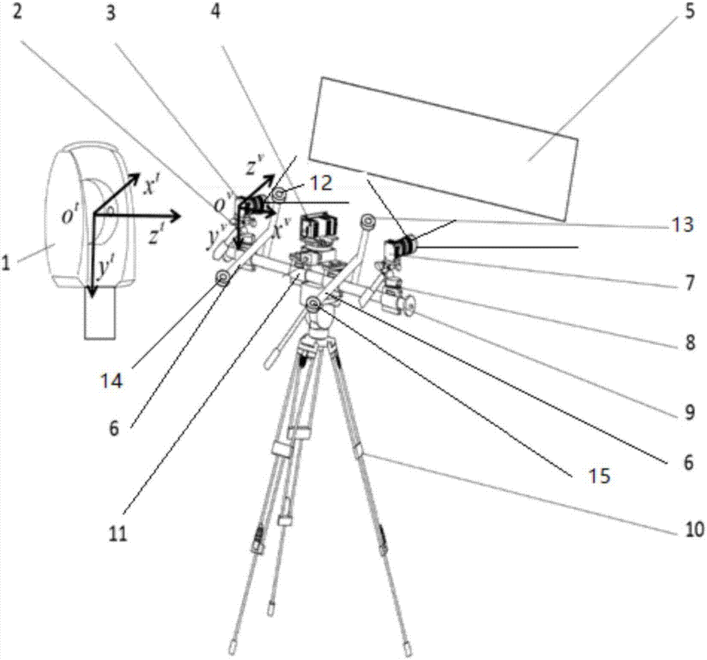
[0048] Embodiment 1, as attached figure 1 As shown, the measuring head 1 of the laser tracker is Leica AT960MR, and the measuring range is 1-20m. The left and right cameras 3 and 7 use VC-12MC-M with a resolution of 3072*4096 and a maximum frame rate of 60Hz.
Login to View More PUM
 Abstract
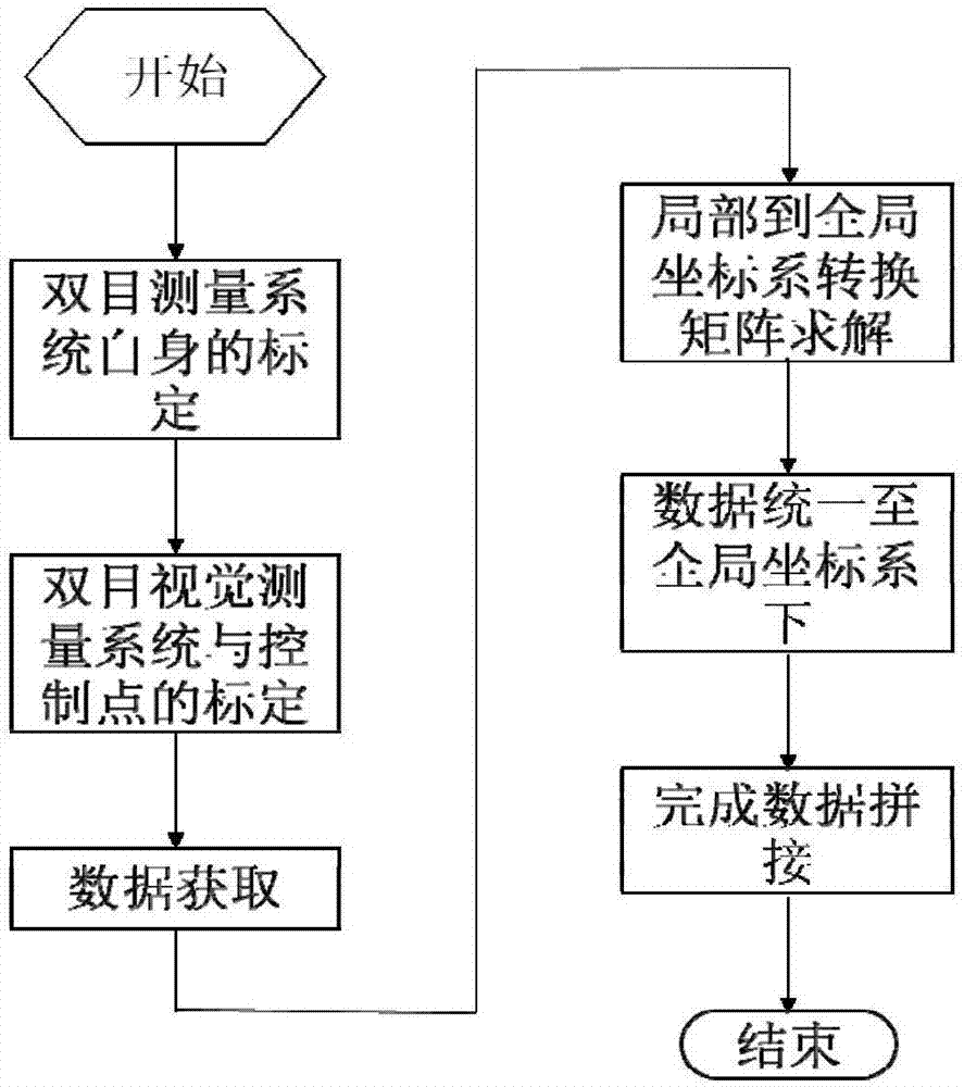
A binocular vision splicing method based on a laser tracker of the invention belongs to the technical field of computer vision measurement, and relates to a binocular vision splicing method based on a laser tracker. 3D data splicing is carried out using a laser tracker and a binocular vision system in the invention. The whole splicing process includes the steps of calibrating the binocular vision system, calibrating a binocular vision measurement system and a control point, data acquisition, and transformation matrix solving. 3D data splicing is completed by transforming measurement data obtained in different positions to a global coordinate system according to the transformation matrix of the data. The method does not need manual arrangement of mark points, and has high measurement efficiency and a large measurement range. The method well combines the high speed of vision measurement and the high measurement precision of the laser tracker. High-precision and fast global measurement of large aircraft parts is realized. The coordinate transformation chain is simple. There is no accumulated error for multi-region measurement. The method is of high applicability.
Description
technical field [0001] The invention belongs to the technical field of computer vision measurement, and relates to a binocular vision splicing method based on a laser tracker Background technique [0002] In the aerospace and other fields, in order to ensure the accuracy and reliability of the assembly and connection of parts, it is usually necessary to perform three-dimensional high-precision measurement of the shape of parts. At present, the machine vision method has been gradually applied to the measurement of large parts such as aerospace due to its advantages of non-contact, fast measurement speed and high precision. The size of aerospace parts can usually reach more than 3m, which greatly exceeds the single-field measurement range of visual measurement, and these parts are usually placed on a specific frame, and there may be occlusion in some directions, so only one The field of view cannot complete the 3D global measurement of the entire component. It is necessary t...
Claims
Login to View More Application Information
Patent Timeline
 Patent Type & Authority Applications(China)
IPC IPC(8): G01B11/24
CPCG01B11/002G01B11/24
Inventor 刘巍兰志广张洋赵海洋叶帆张致远马建伟贾振元
Owner DALIAN UNIV OF TECH