A Direct Contact Heat Dissipation Method for Vibrating Devices Based on Microarray Structure

A technology of microarray structure and vibration device, which is applied in the construction parts of electrical equipment, nanotechnology for materials and surface science, electrical components, etc., can solve the fretting wear of piezoelectric transformer electrode surface contact and reduce the service life of transformer and performance, affecting the performance of the piezoelectric transformer and other issues, to ensure the direct contact area, improve the service life, and improve the effect of heat dissipation

Active Publication Date: 2018-06-29
ANHUI UNIVERSITY
View PDF9 Cites 0 Cited by
  • Summary
  • Abstract
  • Description
  • Claims
  • Application Information

AI Technical Summary

Problems solved by technology

The contact between the piezoelectric transformer and the metal heat sink belongs to the direct contact between two rigid interfaces. Due to the influence of surface defects and roughness, it is impossible to completely fit the contact surfaces. There is an air gap and large thermal resistance, which affects the heat dissipation effect.
At the same time, the piezoelectric transformer is in a state of high-frequency vibration during work, and there is relative sliding between it and the heat sink, which will affect the performance of the piezoelectric transformer; in addition, this high-frequency relative sliding will cause contact fretting wear on the electrode surface of the piezoelectric transformer , greatly reducing the service life and performance of the transformer

Method used


Image

  • A Direct Contact Heat Dissipation Method for Vibrating Devices Based on Microarray Structure
  • A Direct Contact Heat Dissipation Method for Vibrating Devices Based on Microarray Structure
  • A Direct Contact Heat Dissipation Method for Vibrating Devices Based on Microarray Structure

Examples


Embodiment 1

[0030] The following takes carbon nanotube microarray as an example of thermal interface material to explain its application in heat dissipation of piezoelectric transformer in detail:

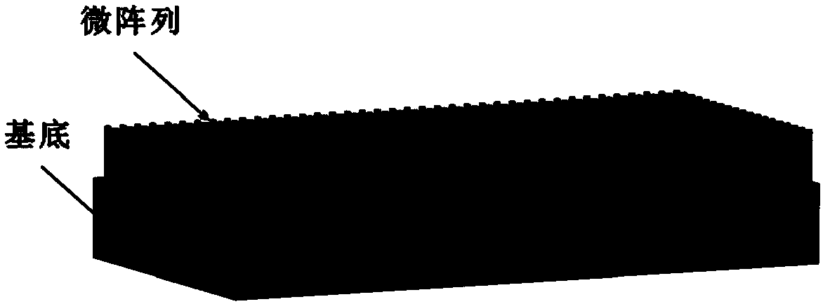
[0031] Figure 1a It shows the microarray structure of carbon nanotubes grown on a rectangular silicon wafer substrate. The carbon nanotubes are vertically arranged and distributed on the substrate. The thermal conductivity measured by laser interferometry is 10-20W / m·K.

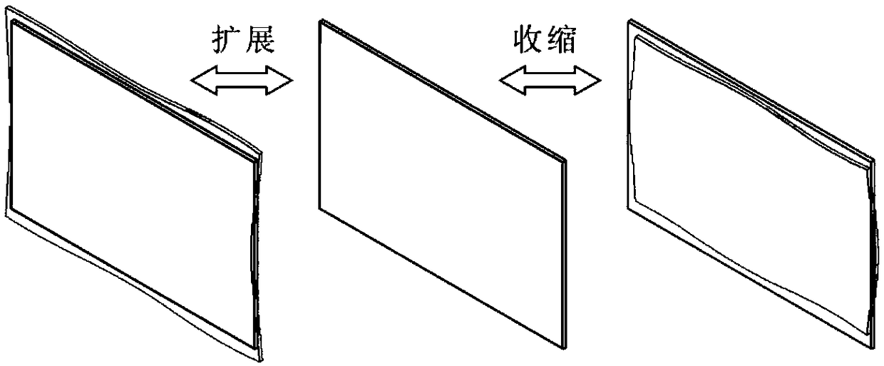
[0032] figure 2 A schematic diagram of the rectangular piezoelectric transformer to be subjected to heat dissipation treatment and its plane expansion mode shape is shown in this embodiment. The piezoelectric transformer is in a state of high-frequency vibration in the lateral direction. If a rigid radiator is directly used for contact heat dissipation, there will be relative sliding between the stationary radiator and the transformer, which will affect the vibration performance of the transformer; at the same time, contac...

Embodiment 2

[0037] Carbon nanotube microarray structure heat dissipation application technical scheme in columnar vibration devices:

[0038] Figure 5 Figure a in Fig. 1 shows a schematic diagram of the torsional vibration mode of the piezoelectric ceramic tube. For this kind of circular vibration device, because it is not in a normal plane motion state, it is usually inconvenient to manage its heat dissipation.

[0039] Figure 5 Figure b in is a schematic diagram of a carbon nanotube microarray structure grown radially on the inner wall of a circular substrate. Based on the high thermal conductivity and high flexibility of the above-mentioned carbon nanotube array, it can reduce the thermal resistance of the contact surface in the application of contact heat dissipation, and there is no relative sliding and no contact wear, so it can be used for thermal management applications of circular vibration devices.

[0040] Figure 6 It is a schematic diagram of the application of the radi...

Embodiment 3

[0042] The following takes copper nanowire microarray as an example of thermal interface material to explain its application in heat dissipation of piezoelectric transformer in detail:

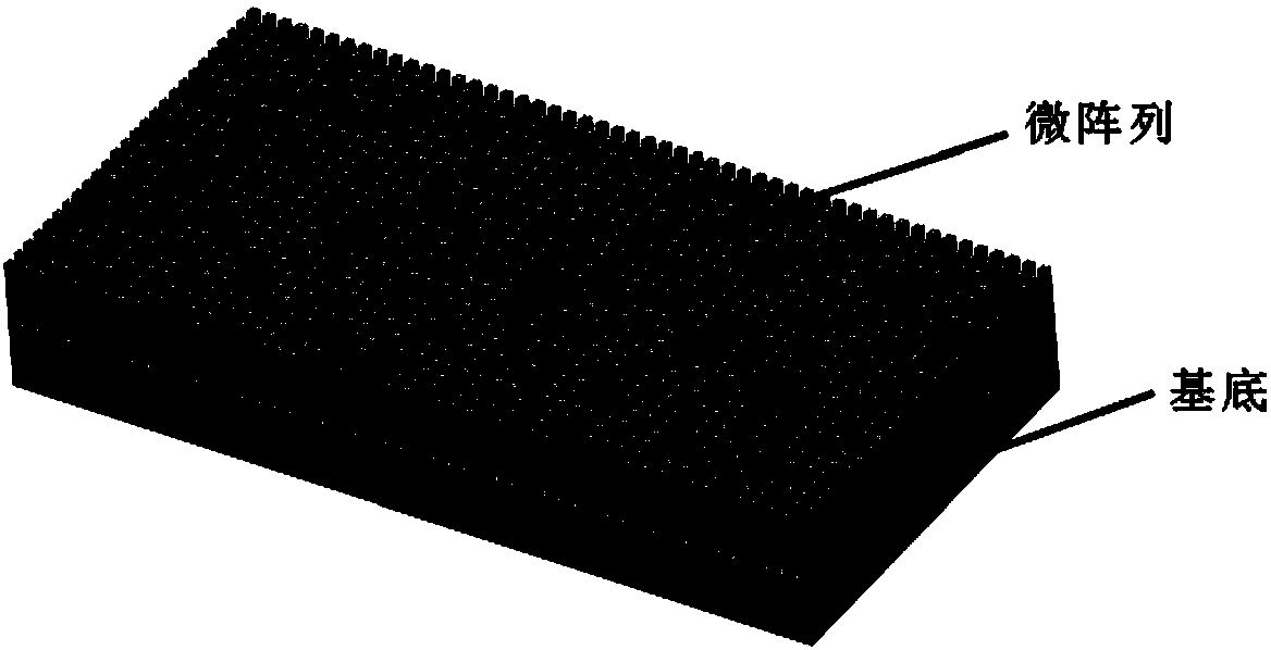
[0043] Figure 1b It shows a copper nanowire microarray structure processed by laser etching or photolithography on a rectangular copper substrate. The copper nanowires are vertically arranged and distributed on the substrate. The unit is a cuboid with a cross-sectional size of about 100 nanometers. The height is in the order of microns, and the array density is about 1%.

[0044] For the piezoelectric transformer in the planar expansion working mode, the copper nanowire microarray structure is used for the embodiment of contact heat dissipation, which can also be used image 3 A schematic diagram showing the heat dissipation structure of the scheme. The piezoelectric transformer is directly in contact with the copper nanowire arrays vertically arranged and distributed on the substrate. The...


PUM


Abstract

The invention discloses a direct contact heat dissipation method and application of a vibration device based on a microarray structure. For a high-frequency vibration device similar to a piezoelectric transformer, direct contact heat dissipation usually has large contact thermal resistance, severe device wear, and affects vibration performance. To solve such problems, an elastic microarray contact heat dissipation structure with low thermal resistance and high thermal conductivity is provided. Through the large-scale growth of a microarray structure with a high aspect ratio and an appropriate array density on the heat sink substrate, based on its good longitudinal thermal conductivity and van der Waals force, as well as good lateral flexibility, it can be used for vibration devices that are not suitable for direct contact heat dissipation occasion. This kind of vibration device thermal management scheme, because there is no relative sliding, no contact wear, high flexibility perpendicular to the heat transfer direction, small damping, low impact on device vibration, and no additional force for fixing in the heat transfer direction, the structure It is simple and can meet the thermal management requirements of vibration devices to a certain extent.

Description

technical field [0001] The invention relates to the thermal management field of microarray structures and vibration devices, in particular to the application of a carbon nanotube array structure in heat dissipation of piezoelectric transformers, that is, a direct contact heat dissipation method and application of a vibration device based on a microarray structure. Background technique [0002] As people's requirements for product portability are getting higher and higher, miniaturization, light weight, and low cost have become an inevitable development trend. However, people's diversified requirements for functions make the power requirements of products higher and higher, so their power density is also higher and higher, and the thermal management of devices is becoming more and more important. For some vibration devices, it is usually not suitable for direct contact heat dissipation, and water cooling or oil cooling is generally used. However, if the vibration device is s...

Claims


Application Information

Patent Timeline
Patent Type & Authority Patents(China)
IPC IPC(8): H05K7/20B82Y30/00B82Y40/00
CPCB82Y30/00B82Y40/00H05K7/2039H05K7/20472H05K7/20481
Inventor 琚斌张海姣郭治华申佳乐刘永斌刘方陆思良
Owner ANHUI UNIVERSITY
Why Eureka
Try Eureka