Cutting and separation head for manual ceramic cutters

A cutting machine and ceramic technology, applied in the direction of manufacturing tools, stone processing tools, stone processing equipment, etc., can solve the problem that ceramic parts cannot be kept in a fixed position, etc.

Active Publication Date: 2017-12-01
GERMANS BOADA SA
View PDF4 Cites 0 Cited by
  • Summary
  • Abstract
  • Description
  • Claims
  • Application Information

AI Technical Summary

Problems solved by technology

[0010] Another disadvantage of this type of separator is that the arrangement between the working position and the non-working position requires manual actuation by the user, which requires both hands to operate, with one hand holding the handle of the cutting and separating head and the other hand Change the position of the separator so that the user cannot hold the ceramic part in a fixed position by hand while cutting the ceramic part with the knife and breaking the ceramic part apart along the cutting line

Method used


Image

  • Cutting and separation head for manual ceramic cutters
  • Cutting and separation head for manual ceramic cutters
  • Cutting and separation head for manual ceramic cutters

Examples


Embodiment Construction

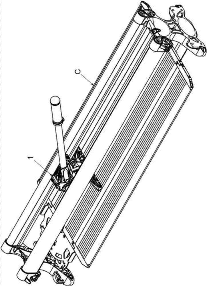
[0028] see figure 1 , which shows a cutting and separating head 1 for ceramic parts in an embodiment, which is installed on a manual ceramic cutting machine C, which can be moved above the cutting machine by longitudinal guide rails arranged in parallel.

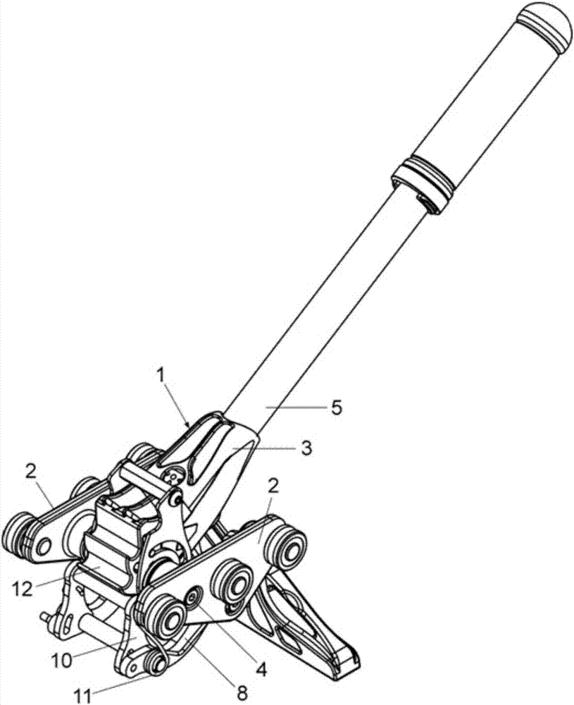
[0029] see figure 2 , which shows a cutting and separating head 1 in an embodiment, which includes a support 2 arranged on both sides thereof and a main body 3 mounted on the support 2, in this embodiment, the support is provided with a rotating Wheels are used to move it on the guide rail of the cutting machine, and the main body is rotatable relative to a first transverse rotation axis 4 . A handle 5 is secured at the first end of the body 3 .

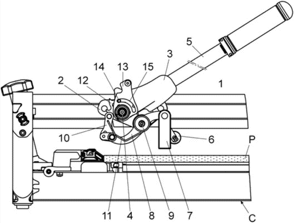
[0030] From Figures 3 to 7 It can be seen more clearly that the lower end of the main body 3 is provided with a cutter 6, which is used for longitudinally cutting the ceramic piece placed at the bottom of the cutting machine, so as to carve a cutting line on the ceramic piece ...


PUM


Abstract

The invention relates to a cutting and separation head for manual ceramic cutters, comprising: a body (3) that carries a grip handle (5) and a cutting tool (6), is mounted on movable supports (2) on longitudinal guides of the cutter (C), and is able to rotate with respect to a first transverse rotary shaft (4); a separator provided with a foot (7), a class 1 lever (8), and a first coupling element (10) in the separator that is couplable to a second coupling element (12) in the body (3) of the head (1); and a cam (13) for releasing the first and second coupling elements (10, 12), the cam being mounted on the body (3) and relatively rotatable between a first position and a second position.

Description

[0001] Purpose of the invention [0002] The object of the present invention is to provide a cutting and separating head of a manual ceramic cutting machine, which, through specific structural features, intends to simplify the movement of the separator so that it can be set just by changing the angle of inclination of the cutting and separating head In the working or non-working position. technical field [0003] The invention is used for manual ceramic cutting machines. Background technique [0004] In the prior art, a manual ceramic cutting machine includes a base and at least one longitudinal guide rail, the base includes a supporting surface for cutting ceramic pieces, and the longitudinal guide rail is provided with a cutting and separating head for cutting ceramic pieces, It is arranged on the base and mounted by a corresponding movable wheel or support. [0005] These cutting and separating heads consist of a body mounted on movable wheels or supports by means of a ...

Claims


Application Information

Patent Timeline
Patent Type & Authority Applications(China)
IPC IPC(8): B28D1/22
CPCB28D1/225
Inventor 乔迪·索勒·巴尔塞尔斯
Owner GERMANS BOADA SA
Why Eureka
Try Eureka