A Bevel Cutting Method of Smaller Size Silicon Block

A silicon block and oblique cutting technology, which is applied in the field of silicon block cutting, can solve the problems of increasing the cost of silicon materials, and achieve the effects of reducing scrap rate, improving work efficiency, and reducing production costs

Inactive Publication Date: 2016-03-30
TIANWEI NEW ENERGY HLDG
View PDF5 Cites 0 Cited by
  • Summary
  • Abstract
  • Description
  • Claims
  • Application Information

AI Technical Summary

Problems solved by technology

[0004] In order to solve the defect that the silicon material cost increases due to the small size of the silicon block, the present invention provides a cutting method for the small size silicon block

Method used


Image

  • A Bevel Cutting Method of Smaller Size Silicon Block
  • A Bevel Cutting Method of Smaller Size Silicon Block
  • A Bevel Cutting Method of Smaller Size Silicon Block

Examples


Embodiment 1

[0030] A bevel cut method for undersized silicon blocks,

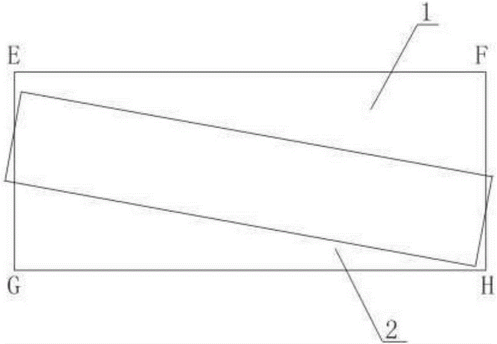
[0031] Such as figure 1 , figure 2 shown, including the following steps:

[0032] Step 1: Select the silicon block to be beveled, measure and record the side length of the smaller side of the silicon block;

[0033] Step 2: Calculate the relative position of bonding the crystal support 2 and the glass plate 1 according to the side length of the smaller side of the silicon block;

[0034] Step 3: According to the calculated data, draw the crystal support boundary line on the glass plate 1, and bond the crystal support 2 to the glass plate 1 according to the crystal support boundary line;

[0035] Step 4: bonding the silicon block on the glass plate 1;

[0036] Step 5: After the silicon block is fixed, the silicon block can be cut, wherein the cutting line is parallel to the short side of the crystal holder 2 .

[0037] In this embodiment, since the length of the hypotenuse is longer than that of the right-angle si...

Embodiment 2

[0039] In this embodiment, on the basis of Embodiment 1, the calculation process of the relative position of the bonding of the crystal support 2 and the glass plate 1 in step 2 is as follows:

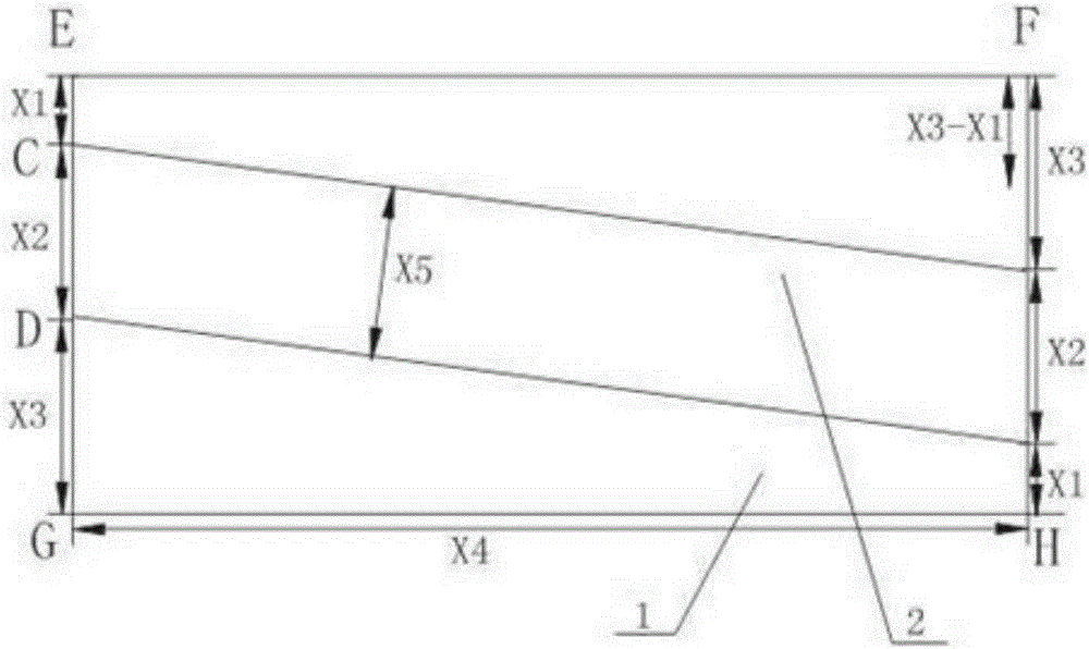
[0040] The four vertices of the glass plate 1 are denoted as E, F, G, H in sequence; the intersection points of the crystal support 2 and one side of the glass plate 1 are respectively C and D.

[0041] according to the formula Calculate the offset length X of the silicon block; wherein Y represents the side length of the smaller side of the silicon block, and B represents the actual length of the silicon block to be achieved;

[0042] according to the formula X 3 X 4 - X 2 X 4 = X Y ;

[0043] x 3 +X 1 =A-X 2 ;

[0044] Cal...

Embodiment 3

[0073] In this embodiment, on the basis of embodiment 2, the side length of the smaller silicon block Y>(2X 5 .B+X.X 4 ) / A.

[0074] When the side length of the small silicon block Y5 .B+X.X 4 ) / A, the size of the silicon block is too small, the relative position deviation between the glass plate 1 and the crystal support 2 is too large, and the actual operation is difficult. In this case, it is not recommended to use bevel cutting. Therefore, by the side length of the smaller side of the silicon block and (2X 5 .B+X.X 4 ) / A, the recyclable scrap silicon blocks can be quickly screened out, which improves work efficiency.


PUM


Abstract

The invention discloses a manner for beveling a silicon block of the small size. The manner comprises the following steps: firstly, the silicon block required to be beveled is selected, and the side length of the small side of the silicon block is measured and recorded; secondly, according to the side length of the small side of the silicon block, the bonding opposite position of a crystal holder and a glass plate is calculated; thirdly, according to data obtained by calculation, a crystal holder border line is drawn on the glass plate, and according to the crystal holder border line, the crystal holder is bonded on the glass plate; fourthly, the silicon block is bonded on the glass plate; and fifthly, the silicon block is fixed, and then can be cut, wherein the cutting line is parallel to the short side of the crystal holder. According to the manner, through beveling, the size problem of the small silicon block can be effectively solved; the rejection rate of the silicon block of the small size can be reduced to the greatest extent, and the cyclic utilization rate of the silicon block is improved; and the production cost is reduced.

Description

technical field [0001] The invention relates to a cutting method of a silicon block, in particular to an oblique cutting method of a small silicon block. Background technique [0002] At present, the production process of silicon wafers for ingot polycrystalline silicon solar cells is generally: spraying and charging → ingot casting → ingot breaking → testing and processing → slicing → cleaning → sorting. [0003] In the process of processing silicon blocks, the size of silicon blocks is often small due to improper operation. Generally, silicon blocks with a large size can be ground to a normal size through later surface grinding, but silicon blocks with a smaller size can only be scrapped, which will lead to an increase in the cost of the silicon material. According to experiments, the electrical properties of smaller silicon blocks meet the product requirements except that the size does not meet the requirements. Direct scrapping will lead to an increase in the cost of si...

Claims


Application Information

Patent Timeline
Patent Type & Authority Patents(China)
IPC IPC(8): B28D5/00
CPCB28D5/0052B28D5/045
Inventor 钟树敏鲜杰刘兴翀林洪峰
Owner TIANWEI NEW ENERGY HLDG
Why Eureka
Try Eureka