Vortex fluid machinery

A fluid machinery and vortex technology, which is used in rotary piston machinery, mechanical equipment, liquid fuel engines, etc., can solve problems such as volume imbalance and efficiency drop, and achieve the effect of eliminating mixing loss.

Active Publication Date: 2020-01-14
MITSUBISHI HEAVY IND THERMAL SYST
View PDF8 Cites 0 Cited by
  • Summary
  • Abstract
  • Description
  • Claims
  • Application Information

AI Technical Summary

Problems solved by technology

However, the pair of compression chambers has an asymmetric shape due to the presence or absence of the step portion, and the volume is unbalanced. After the pair of compression chambers end suction and start compression, when the engagement between the step portions is disengaged and the two compression chambers communicate, A differential pressure is created between the two compression chambers
Mixing loss occurs due to this differential pressure, and there are problems such as a decrease in efficiency corresponding to it.

Method used


Image

  • Vortex fluid machinery
  • Vortex fluid machinery
  • Vortex fluid machinery

Examples


no. 1 approach

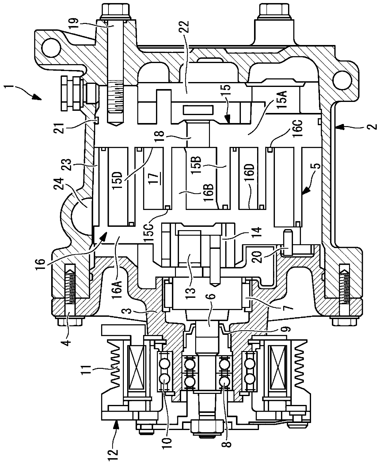
[0041] Below, use Figure 1 to Figure 5 A first embodiment of the present invention will be described.

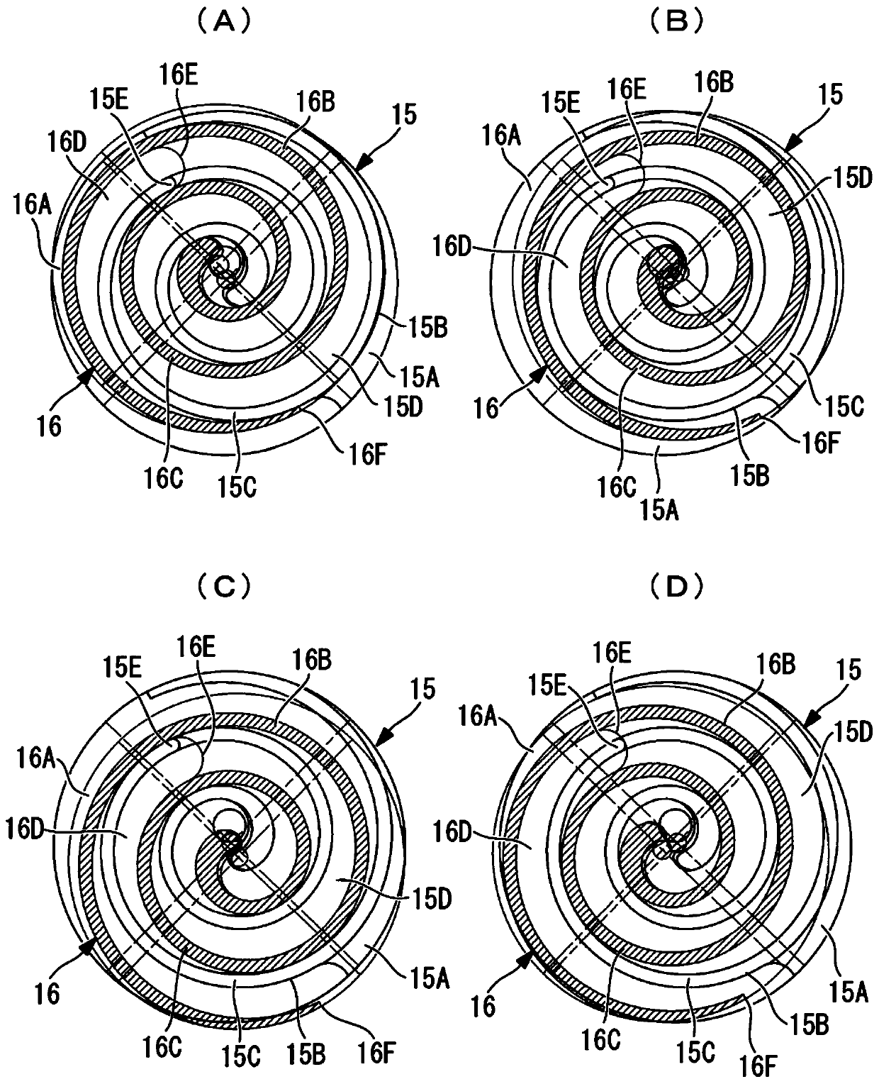
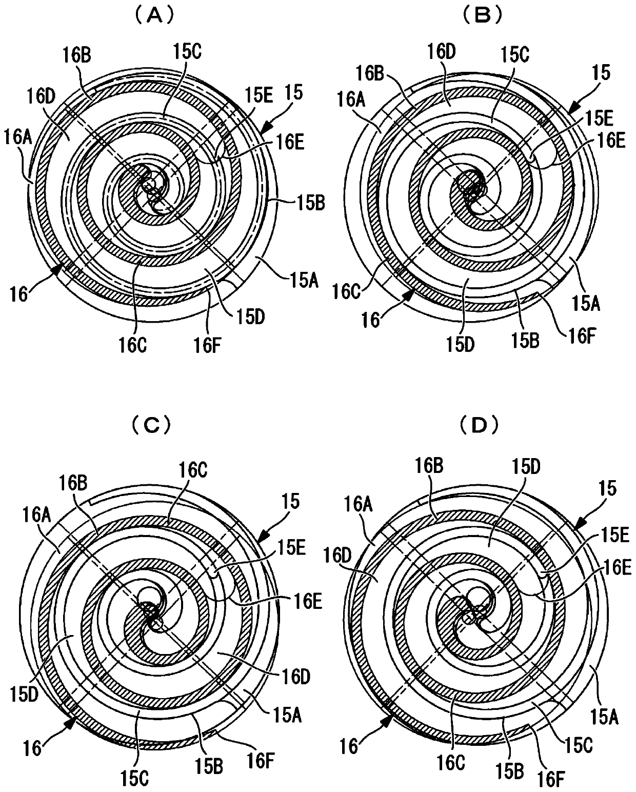
[0042]figure 1 A longitudinal sectional view showing a scroll fluid machine according to a first embodiment of the present invention, figure 2 The explanatory diagram of the meshing state of the fixed scroll and the orbiting scroll at different orbital angle positions is shown as figure 2 (A) to figure 2 (D).

[0043] Here, as an example of a scroll fluid machine, an example of application to an open scroll compressor (scroll fluid machine) 1 of a type driven by external power will be described.

[0044] Such as figure 1 As shown, an open scroll compressor (scroll fluid machine) 1 includes a casing 2 constituting an outer contour. The housing 2 is in a cylindrical shape in which an opening is formed on the front end side and the rear end side is sealed. The front housing 3 is fastened and fixed to the opening on the front end side by bolts 4 to form a closed space i...


PUM


Abstract

A scroll fluid machine includes a pair of a fixed scroll (15) and an orbiting scroll (16). The scroll fluid machine has an one-side stepped scroll structure in which a stepped part (16E) is provided only at a predetermined position on a tooth bottom surface (16D) of a involute spiral wrap (16B) of one of the fixed scroll (15) and the orbiting scroll (16) in a spiral direction, and a stepped part (15E) corresponding to the stepped part (16E) on the tooth bottom surface (16D) is provided only at a predetermined position on a tooth top surface (15C) of a involute spiral wrap (15B) of the other scroll in a spiral direction. The stepped part (16E) on the tooth bottom surface (16D) is provided at a position on an inner side of a spiral end position (16F) of the involute spiral wrap (16B) at intake closure by an involute angle of n radians in the spiral direction or at a position on an outer side of the inner-side position.

Description

technical field [0001] The present invention relates to a scroll fluid machine that can be applied to compressors, pumps, expanders, and the like. Background technique [0002] The scroll fluid machine has a pair of fixed scroll and an orbiting scroll with spiral teeth erected on the end plate. The spiral teeth of the pair of fixed scroll and orbiting scroll face each other. And staggered 180 degrees of phase to mesh, thus forming a pair of compression chambers between the two turbine parts, forming a structure for supplying and discharging fluid. In the above-mentioned scroll fluid machine, for example, a scroll compressor, generally adopts a two-dimensional compression structure as follows: The circumferential height is set to be uniform, and the volume of the compression chamber is reduced from the outer peripheral side to the inner peripheral side to move, and the fluid sucked into the compression chamber is compressed along the circumferential direction of the scroll t...

Claims


Application Information

Patent Timeline
Patent Type & Authority Patents(China)
IPC IPC(8): F04C18/02
CPCF04C18/0215F04C18/0276F04C29/0064F04C18/02F01C1/0215
Inventor 萩田贵幸桑原孝幸藤田胜博竹内真实庆川源太山崎浩北口惠太佐藤创
Owner MITSUBISHI HEAVY IND THERMAL SYST
Why Eureka
Try Eureka