Multiple channel diffuser

a diffuser and multi-channel technology, applied in the direction of non-positive displacement fluid engines, pump components, radial flow pumps, etc., can solve the problem of significant increase in the chamber pressure for additional stage capability, and achieve the effect of reducing mixing losses, increasing pressure recovery, and increasing chamber pressur

Active Publication Date: 2020-06-16
P3 TECH LLC
View PDF6 Cites 3 Cited by
  • Summary
  • Abstract
  • Description
  • Claims
  • Application Information

AI Technical Summary

Benefits of technology

[0007]The Multiple Channel Diffuser of the present invention eliminates mixing losses, resulting in a significant increase in pressure recovery (such as around 20% or greater). The impeller discharge pressure is expanded gradually and efficiently in discrete passages. Once the flow has been fully expanded, it is merged and combined with adjacent passages. However, because the flow is fully expanded (and because there is no turning), there are no significant pressure or velocity gradients to cause mixing losses. Holding the pump or compressor, engine size, and stage constant, this results is a significant increase in chamber pressure for additional stage capability (higher orbits, higher orbit inclinations, and / or heavier payloads). Alternatively, holding the specific impulse and thrust constant, both the maximum diameter and overall length shrink significantly, resulting in a smaller, lower weight stage with a significant increase in mission capability.

Problems solved by technology

Holding the pump or compressor, engine size, and stage constant, this results is a significant increase in chamber pressure for additional stage capability (higher orbits, higher orbit inclinations, and / or heavier payloads).

Method used


Image

  • Multiple channel diffuser
  • Multiple channel diffuser
  • Multiple channel diffuser

Examples


Embodiment Construction

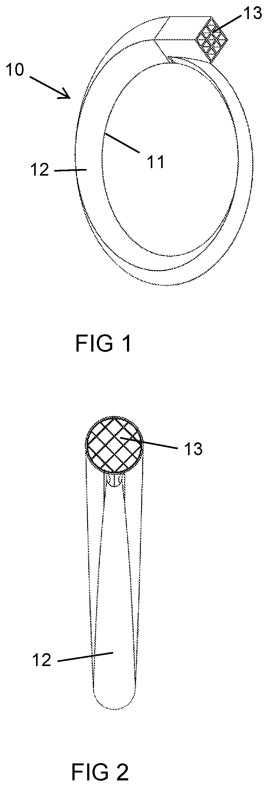
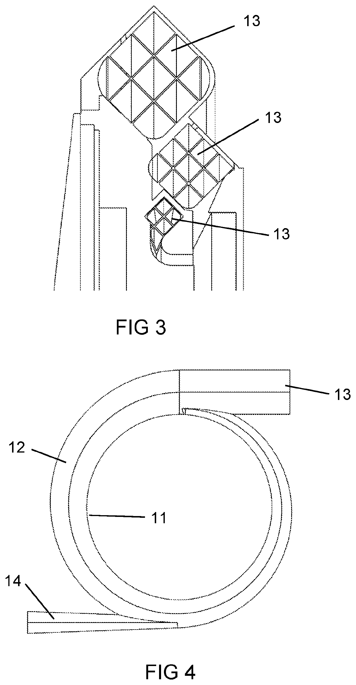
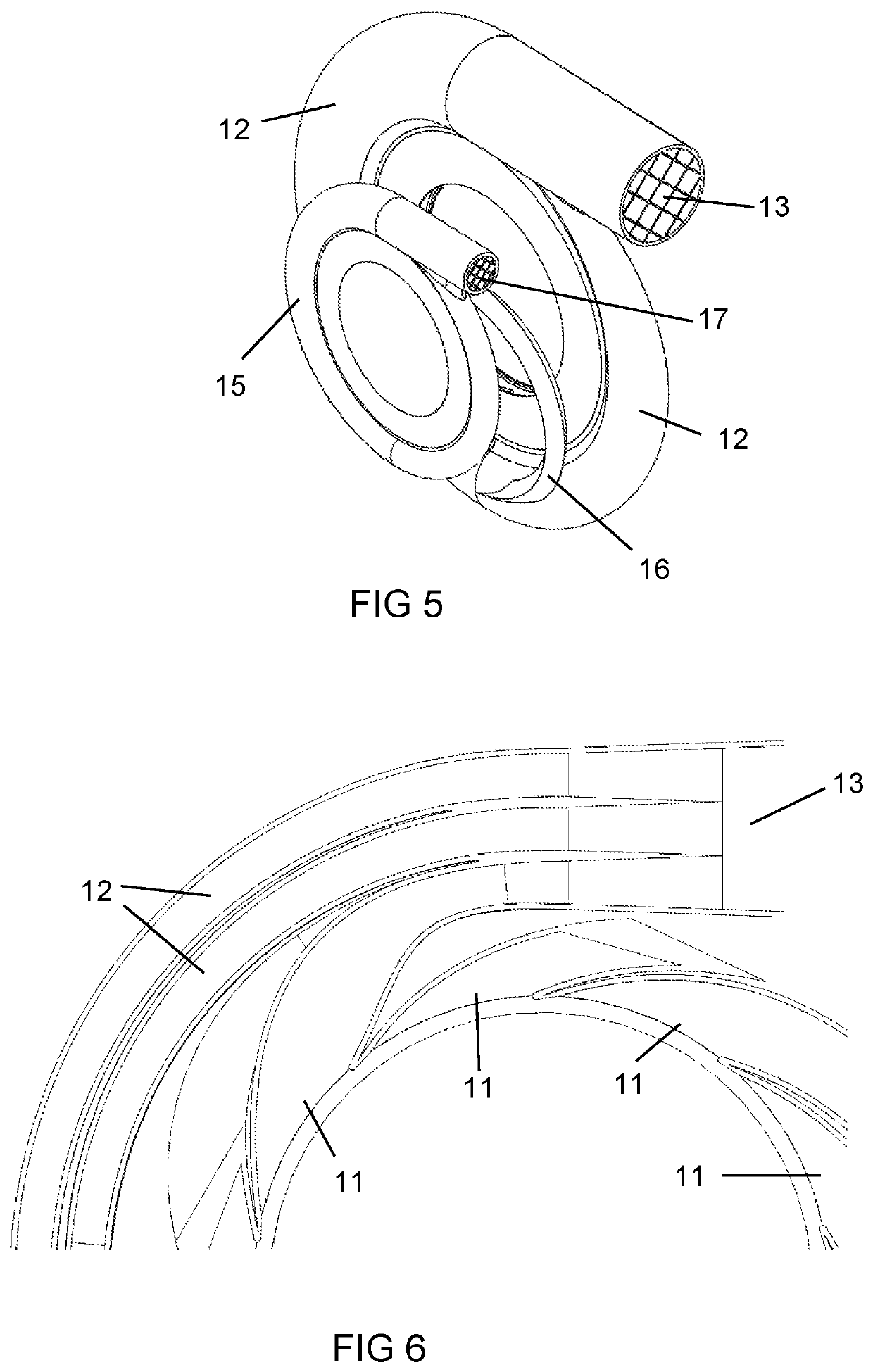
[0024]The present invention is a Multiple Channel Diffuser (MCD) for a pump or a compressor such as a turbopump with an annular shaped radial inlet and a tangential outlet where the multiple passages are separate from one another in order to limit mixing of the fluid. FIG. 1 shows one such embodiment of the MCD 10 with an outlet having a square cross section shape with nine separate passages. The MCD includes an annular shaped radial inlets 11 in which each inlet 11 is connected to a separate passage 12 that leads to a common outlet 13. The separate passages 12 each have a gradually increasing cross sectional area from the inlet to the outlet to produce individual diffusers without mixing of fluids. An impeller discharges a fluid outward in an annular arrangement and into the separate radial inlets of the MCD 10. Each inlet 11 is connected to its own separate passage 12 and opens into a common outlet 13. The impeller rotates within the stationary MCD.

[0025]The MCD of the present inv...


PUM


Abstract

A multiple channel diffuser having an annular shaped radial inlet and a tangential outlet, and a plurality of separated diffuser channels connecting the radial inlet to the tangential outlet such that a flow does not mix. A tap-off passage can be used to provide flow to a gas generator or a preburner. A cross-over passage can also be used to provide flow from a first diffuser to a second diffuser.

Description

CROSS-REFERENCE TO RELATED APPLICATIONS[0001]None.GOVERNMENT LICENSE RIGHTS[0002]None.BACKGROUND OF THE INVENTIONField of the Invention[0003]The present invention relates generally to a pump or compressor, and more specifically to a diffuser for a pump or compressor.Description of the Related Art Including Information Disclosed Under 37 CFR 1.97 and 1.98[0004]A pump or a compressor such as a Turbopump uses a diffuser to convert the dynamic pressure exiting the pump or compressor into static pressure rise at the volute exit. There are three commonly used diffusers: vaneless diffusers, airfoil diffusers, and vane island diffusers. FIG. 10 shows a vane island diffuser. FIG. 11 shows an airfoil diffuser. FIG. 12 shows a vaneless diffuser. The single greatest loss in a turbopump is in the diffuser. The diffuser losses account for more than 20% of the total pressure loss from the impeller discharge to the volute. The losses are from the leading edge (incidence loss), the trailing edge (ex...

Claims


Application Information

Patent Timeline
Patent Type & Authority Patents(United States)
IPC IPC(8): F04D29/44F04D1/06F04D29/66
CPCF04D29/44F04D29/441F04D1/063F04D29/445F04D29/669
Inventor DEMSKI, BRANDON A
Owner P3 TECH LLC
Why Eureka
Try Eureka