Hydraulic auto-tensioner

A tensioner, hydraulic technology, applied in the field of hydraulic automatic tensioners, can solve problems such as shredding

Active Publication Date: 2017-12-01
NTN CORP
View PDF8 Cites 1 Cited by
  • Summary
  • Abstract
  • Description
  • Claims
  • Application Information

AI Technical Summary

Problems solved by technology

Therefore, when the tension of the belt is adjusted under the use state of the hydraulic automatic tensioner, the dust-proof lip 62 provided on the oil seal 61 may be pulled into the chrysanthemum ring through the relative sliding and inclination of the cylinder 60 and the rod 64 63 center hole 63c and be shredded

Method used


Image

  • Hydraulic auto-tensioner
  • Hydraulic auto-tensioner
  • Hydraulic auto-tensioner

Examples


Embodiment Construction

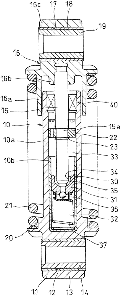
[0023] Embodiments of the present invention will be described below based on the drawings. Such as figure 1 As shown, the cylinder block 10 is composed of an outer cylinder 10a and a bottomed inner cylinder 10b fitted inside the outer cylinder 10a. The outer cylinder 10a is made of aluminum or aluminum alloy and molded by die casting. On the other hand, the inner cylinder 10b is made of hard metal such as stainless steel.

[0024] A connecting piece 11 is provided at the closed end of the outer cylinder 10a. A connecting hole 12 penetrating both side surfaces is formed in the connecting piece 11 , and a sleeve 14 is rotatably incorporated in the connecting hole 12 via a slide bearing 13 .

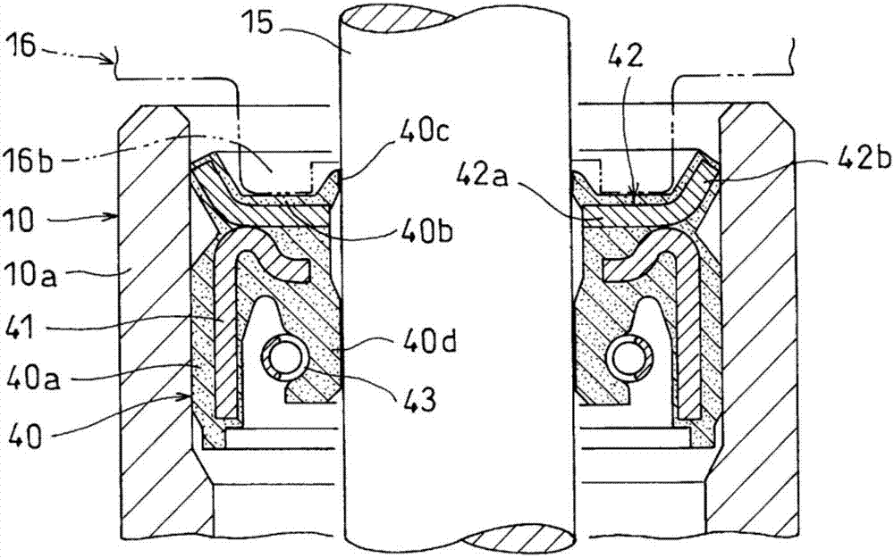
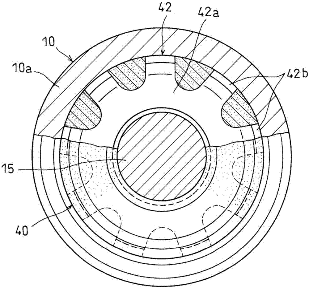
[0025] Hydraulic oil is filled in the cylinder 10 . In addition, a rod 15 is inserted into the cylinder 10 , and a spring seat 16 is attached to an end of the rod 15 protruding from the open end of the cylinder 10 to the outside. The spring seat 16 is provided with a cylindrical skirt ...


PUM


Abstract

In the present invention a rod (15) is inserted into a bottomed cylinder (10) filled with operating oil, and a hydraulic damper (30) that absorbs pressing force in the direction causing the cylinder (10) and the rod (15) to retract relative to one another is provided in the cylinder (10). A cogwheel-shaped retaining ring (42) is formed integrally with an oil seal (40) sealing the end opening of the cylinder (10), thereby preventing a dust lip (40c) provided at the inner circumference of the oil seal (40) from being pulled into a center hole of the cogwheel-shaped retaining ring (42) by relative axial movement or relative tilting of the rod (15) and the cylinder (10).

Description

technical field [0001] The present invention relates to a hydraulic automatic tensioner for adjusting the tension of a belt for driving an auxiliary machine such as an alternator, a water pump, and an air conditioner compressor, and a timing belt for driving a camshaft. Background technique [0002] Conventionally, as such a hydraulic automatic tensioner, the hydraulic automatic tensioner described in the following patent document 1 is known. In this hydraulic automatic tensioner, a rod is inserted into a cylinder filled with working oil, and a spring seat provided at the end of the rod and a flange provided at the end periphery of the closed end side of the cylinder are inserted. A back-moving spring is inserted between them, and the cylinder body and the rod are exerted force in a relatively elongated direction by the back-moving spring. [0003] In addition, a hydraulic damper is provided inside the cylinder, and the thrusting force in the direction of shrinking the cyli...

Claims


Application Information

Patent Timeline
Patent Type & Authority Applications(China)
IPC IPC(8): F16H7/08F16J15/3204
CPCF16H7/08F16J15/3204F16J15/3252F16J15/3276F16F1/00F16F9/36F16H7/0836F16H7/0848F16H2007/0812F16H2007/0859F15B15/1461F16J15/3208
Inventor 望月雄太北野聪
Owner NTN CORP
Why Eureka
Try Eureka