Rotor of a rotating electrical machine

A technology of rotating electrical machines and rotors, which is applied in the field of rotors of rotating electrical machines, which can solve the problems of increased reluctance torque and achieve the effect of increasing the salient pole ratio

Active Publication Date: 2020-06-12
TOYOTA IND CORP
View PDF7 Cites 0 Cited by
  • Summary
  • Abstract
  • Description
  • Claims
  • Application Information

AI Technical Summary

Problems solved by technology

[0004] However, it is desired to further increase the reluctance torque by effectively utilizing the rotor core

Method used


Image

  • Rotor of a rotating electrical machine
  • Rotor of a rotating electrical machine
  • Rotor of a rotating electrical machine

Examples


Embodiment Construction

[0023] Hereinafter, one embodiment of the present invention will be described with reference to the drawings.

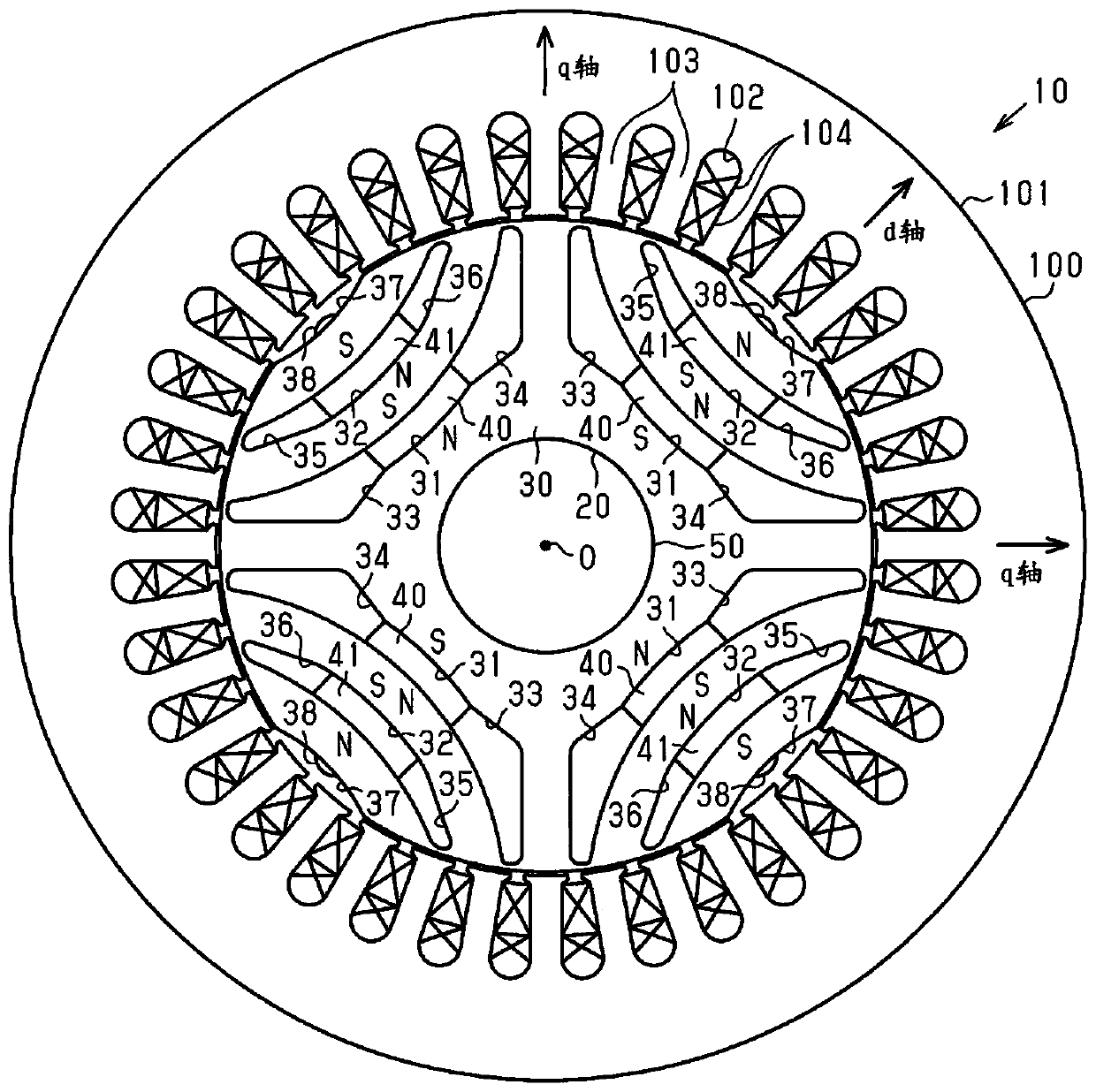
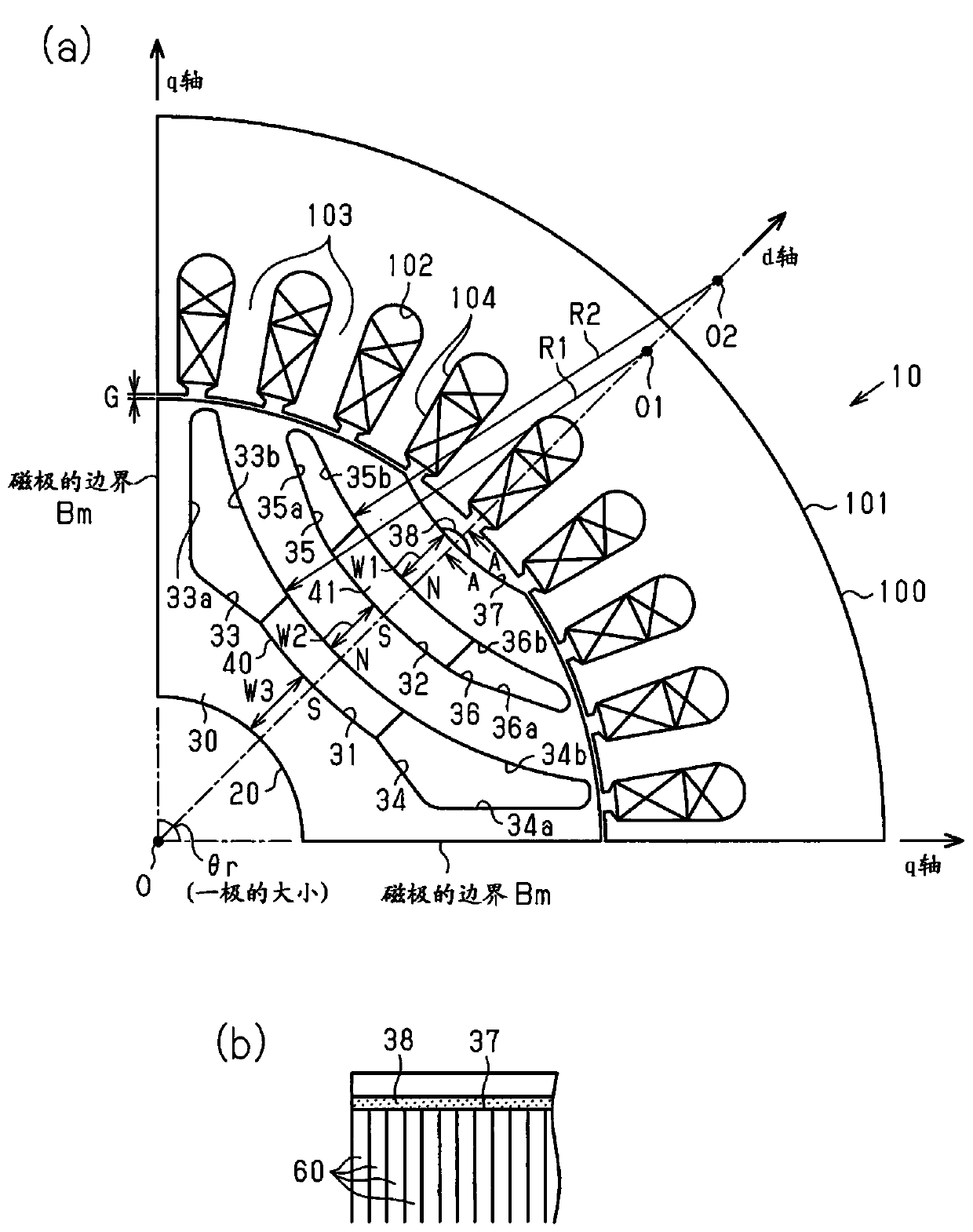
[0024] Such as figure 1 As shown, the rotating electrical machine 10 is a magnet-embedded rotating electrical machine, and includes a rotor 20 and a stator 100 . The stator 100 is disposed on the outer peripheral side of the cylindrical rotor 20 . The inner peripheral surface of the stator 100 passes through the gap G (refer to figure 2 (a)) faces the outer peripheral surface of the rotor 20 . In addition, the figure is all a schematic diagram, and describes it emphatically about a shape. The number of poles of the rotating electric machine 10 of this embodiment is "4".

[0025] Such as figure 1 as well as figure 2 As shown in (a), the stator 100 has a cylindrical stator core 101 , and a plurality of (36 in this embodiment) slots 102 are formed inside the stator core 101 so as to line up in the circumferential direction. Each slot 102 opens on the inner pe...


PUM


Abstract

The present invention provides a rotor of a rotating electric machine, comprising a cylindrical rotor core disposed radially inside a stator around which coils are wound, and an outer peripheral surface of the rotor core faces the stator via a gap. The rotor core has a plurality of magnetic pole regions in the circumferential direction, and has a magnetic flux barrier extending along the q-axis magnetic circuit in each magnetic pole region. The inner wall of the flux barrier has a radially outer wall surface and a radially inner wall surface, the radially inner wall surface expanding toward an adjacent magnetic pole region compared to a position along the q-axis magnetic circuit.

Description

technical field [0001] This invention relates to rotors for rotating electric machines. Background technique [0002] There is a rotor of a rotating electrical machine in which an arcuate magnetic flux barrier is formed on a rotor core (for example, Patent Document 1). In the motor disclosed in Patent Document 1, such as Figure 14 As shown, by providing the arc-shaped slot 201 in the rotor core 200, the saliency ratio (Lq / Ld) is increased, thereby increasing the reluctance torque. [0003] Patent Document 1: Japanese Patent Laid-Open No. 2013-179765 [0004] However, it is desired to further increase the reluctance torque by effectively utilizing the rotor core. Contents of the invention [0005] An object of the present invention is to provide a rotor for a rotating electrical machine capable of increasing the saliency ratio. [0006] A rotor of a rotating electric machine for solving the above-mentioned problems has a cylindrical rotor core configured to be disposed ...

Claims


Application Information

Patent Timeline
Patent Type & Authority Patents(China)
IPC IPC(8): H02K1/27H02K1/22H02K19/10
CPCH02K1/27H02K21/14H02K29/03H02K1/276H02K2213/03H02K1/246H02K2201/03
Inventor 樋田直孝草留泰三下河元希
Owner TOYOTA IND CORP
Why Eureka
Try Eureka