A high-speed permanent magnet motor rotor including an axially stressed magnetically permeable sheath

A technology of permanent magnet motor and axial force, applied in the direction of magnetic circuit rotating parts, magnetic circuit, electromechanical devices, etc., can solve the problems of low magnetic load of high-speed permanent magnet motor, large eddy current loss of rotor, poor heat dissipation of rotor structure, etc. , to achieve the effect of reducing the temperature rise of the rotor, increasing the speed, and improving the torque output capability of the motor

Active Publication Date: 2020-11-03
SOUTHEAST UNIV
View PDF4 Cites 1 Cited by
  • Summary
  • Abstract
  • Description
  • Claims
  • Application Information

AI Technical Summary

Problems solved by technology

[0006] Aiming at the defects of the above-mentioned prior art, the present invention provides a high-speed permanent magnet motor rotor including an axially stressed magnetically conductive sheath, which solves the problem of low magnetic load, poor heat dissipation of the rotor structure, and large rotor eddy current loss in the existing high-speed permanent magnet motor And other issues

Method used


Image

  • A high-speed permanent magnet motor rotor including an axially stressed magnetically permeable sheath
  • A high-speed permanent magnet motor rotor including an axially stressed magnetically permeable sheath
  • A high-speed permanent magnet motor rotor including an axially stressed magnetically permeable sheath

Examples


Embodiment Construction

[0020] The present invention will be further described below in conjunction with embodiment, should be understood that these embodiments are only used to illustrate the present invention and are not intended to limit the scope of the present invention, after having read the present invention, those skilled in the art can modify various equivalent forms of the present invention All fall within the scope defined by the appended claims of this application.

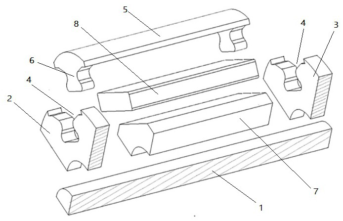
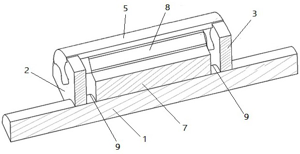
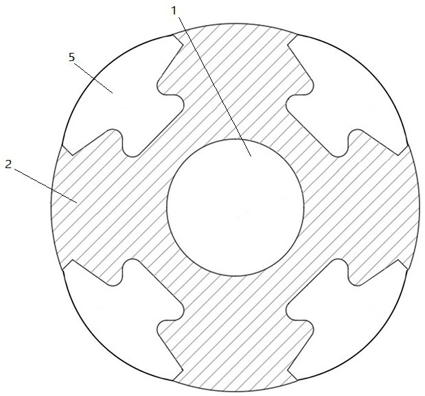
[0021] Please combine Figure 1 to Figure 4 As shown, the rotor of the high-speed permanent magnet motor comprising the axially stressed magnetic-conducting sheath involved in this embodiment is a quadrupole rotor. The hoop plate 2 and the rear hoop plate 3, the rotating shaft 1, the front hoop plate 2 and the rear hoop plate 3 are all made of non-magnetic materials, such as GH4169 high-strength alloy steel. Four circumferentially opposite grooves 4 are set on the front hoop 2 and the rear hoop 3, and four magnetically condu...


PUM


Abstract

The invention discloses a high-speed permanent magnet motor including an axial-forced magnetic-conductive jacket. The high-speed permanent magnet motor comprises a rotating shaft, a front hooped plateand a back hooped plate are arranged on an axial direction of the rotating shaft; two ends of a plurality of magnetic-conductive jacket plate plates are fixedly connected with the front hooped plateand the back hooped plate to form electric insulation; a rotor iron core is arranged between the front hooped plate and the back hooped plate and fixedly connected with the rotating shaft; the permanent magnet is fixedly arranged between the roto iron core and each magnetic conductive jacket plate; the amount of each of the magnetic conductive jacket plate and the permanent magnet is same as the pole number of the rotor; each of the front hooped plate and the back hooped plate is made from non-magnetic conductive material, a first clearance is formed between the adjacent magnetic conductive jacket plates, a second clearance is formed between the adjacent permanent magnets, and the third clearance is arranged among the permanent magnet and the front hooped plate and the third hooped plate.The structure disclosed by the invention can reduce the eddy loss in the jacket, inhibit the rotor temperature rising, and improves the magnetic load and torque output capacity of the motor at the same time.

Description

technical field [0001] The invention relates to a motor rotor, in particular to a high-speed permanent magnet motor rotor including an axial force magnetic conduction sheath, which belongs to the technical field of motors. Background technique [0002] In the application field of high-speed permanent magnet motors, the usability of the embedded rotor structure is not good due to the influence of the strength of the rotor iron core lamination and the magnetic bridge leakage. When the surface speed of the rotor exceeds a certain value, the rotor of the high-speed permanent magnet motor generally adopts a surface-mounted structure. The surface-mounted permanent magnet is pasted or set on the rotor core. In order to offset the centrifugal force on the permanent magnet, a non-magnetic sheath is placed on the periphery of the permanent magnet, and an interference fit is adopted between the non-magnetic sheath and the permanent magnet. . The motor shaft of the surface-mounted str...

Claims


Application Information

Patent Timeline
Patent Type & Authority Patents(China)
IPC IPC(8): H02K1/27H02K11/028
CPCH02K1/2706H02K11/028
Inventor 黄允凯祝子冲
Owner SOUTHEAST UNIV
Why Eureka
Try Eureka