Motor

A neodymium iron boron and stator technology, used in electric components, electrical components, electromechanical devices, etc., can solve the problems of low salient pole rate and rotor demagnetization, and achieve the effect of increasing salient pole rate, reducing eddy current and increasing Lq

Pending Publication Date: 2020-02-07
CHANGZHOU GOLDEN MOTOR TECH
View PDF0 Cites 1 Cited by
  • Summary
  • Abstract
  • Description
  • Claims
  • Application Information

AI Technical Summary

Problems solved by technology

[0004] In order to solve the technical problems that the rotor of the disc motor existing in the prior art is prone to generate eddy currents in the magnetic field, causing the rotor to demagnetize; the saliency rate is low, the present invention proposes a motor that solves the above technical problems

Method used


Image

  • Motor
  • Motor
  • Motor

Examples


Embodiment 1

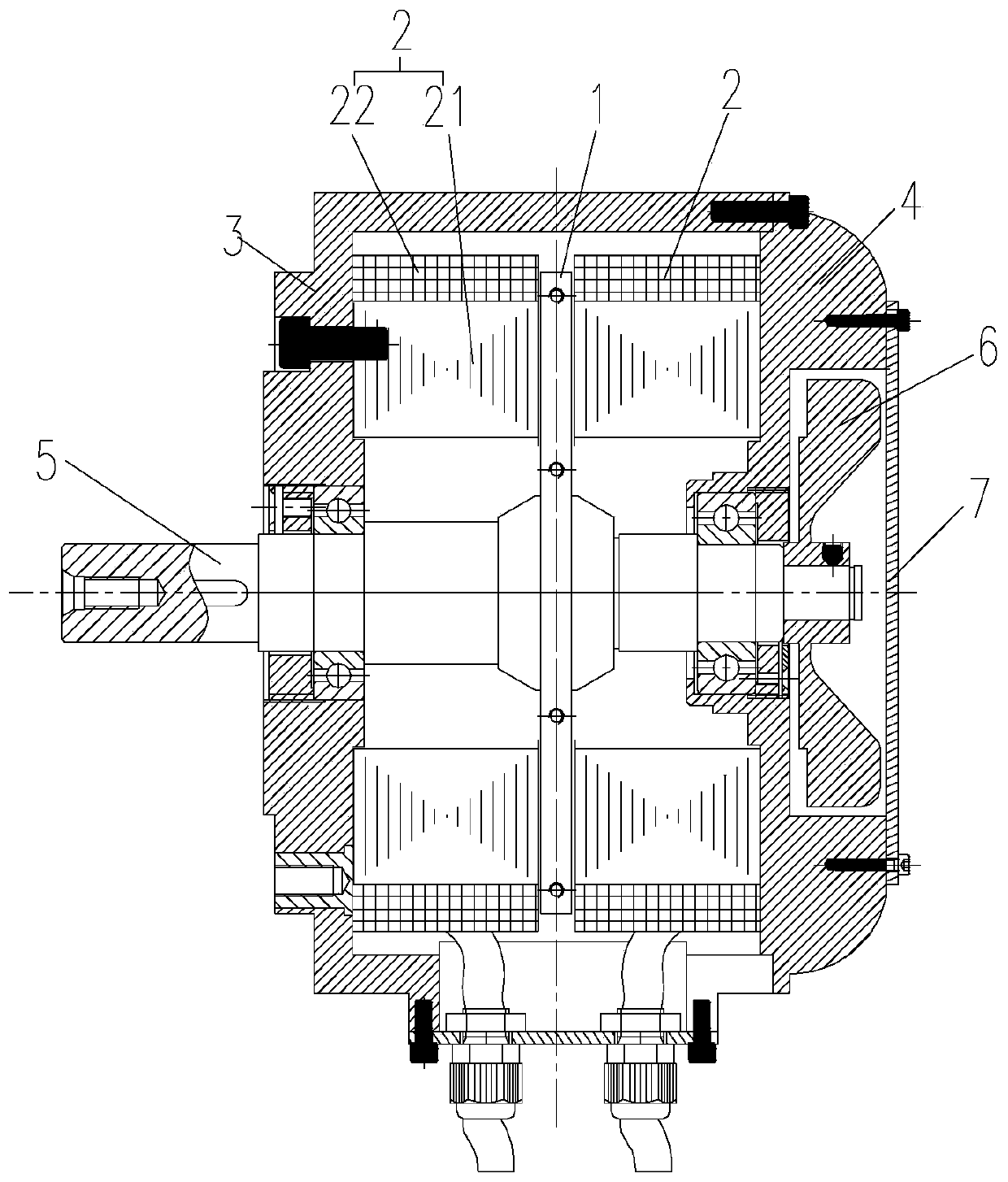
[0039] Such as Figure 3-8 As shown, the present embodiment provides a motor, specifically a disc motor, including a rotor 1 and a stator 2 , there are two stators 2 , and the rotor 1 is axially interposed between the two stators 2 . Specifically, the motor includes a casing 3 and an end cover 4, and the casing 3 and the end cover 4 are fixedly connected to form a cavity with an accommodation space, the rotor 1 and the stator 2 are both placed in the cavity, and the two stators 2 are respectively fixed on the sides of the casing 3 On the inner wall of the inner wall and the inner wall of the end cover 4, the rotor 1 is rotatably arranged between the two stators 2, the rotor 1 is rotatably arranged through the rotating shaft 5, and the two ends of the rotating shaft 5 are respectively rotatably arranged on the casing 3 and the end cover 4 through bearings superior.

[0040] The rotor 1 includes a rotor bracket 11, a NdFeB permanent magnet 12 and a ferrite magnet 13, the NdFeB ...

Embodiment 2

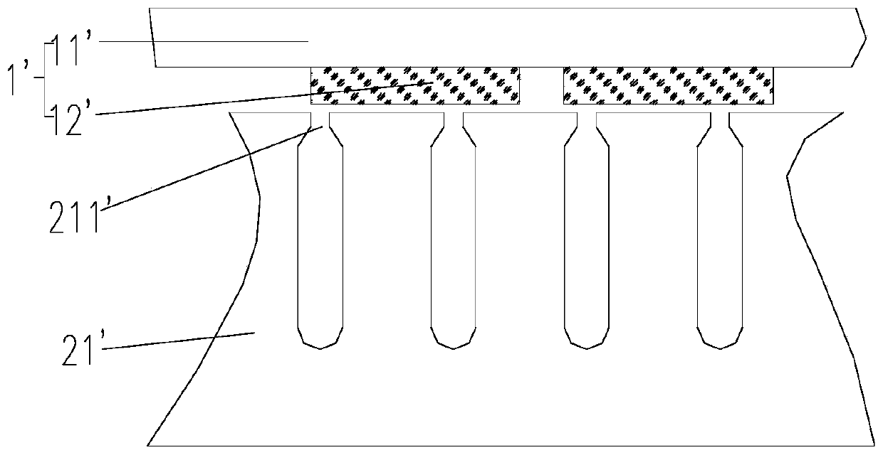
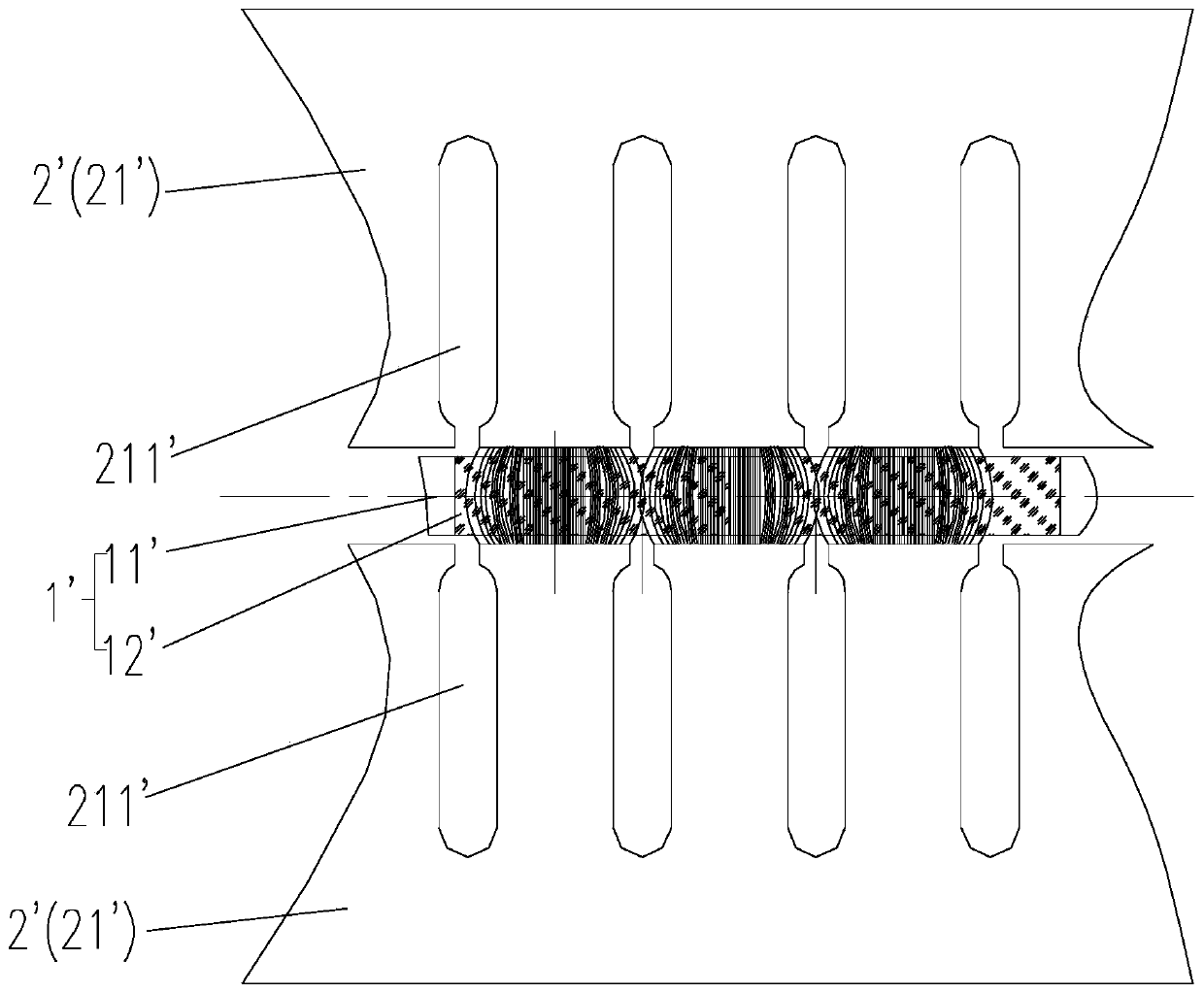
[0052] Such as Figure 9-12 As shown, this embodiment is basically the same as Embodiment 1, the only difference is that, in the rotor 1 of this embodiment, only one axial side of the rotor support 11 is distributed with NdFeB permanent magnets 12, and the NdFeB permanent magnets 12 are far away from the rotor. The axial sides of the bracket 11 are covered with ferrite magnets 13 . Specifically, there is no need to provide installation holes 111 and receiving holes on the rotor bracket 11 , and the NdFeB permanent magnets 12 can be surface-attached on one axial side of the rotor bracket 11 and distributed circumferentially. The pole piece 14 is surface-attached on the same axial side of the rotor support 11 , and the pole piece 14 is located between two adjacent NdFeB permanent magnets 12 .

[0053] In the motor of this embodiment, the rotor 1 is matched with a stator 2, and the stator 2 is arranged on the side of the rotor 1 close to the ferrite magnet 13. By setting the fer...


PUM


Abstract

The invention relates to a motor and particularly relates to the motor. The motor comprises a rotor and a stator which are matched with each other, the rotor includes a rotor bracket, neodymium iron boron permanent magnets, ferrite magnets and pole shoes, the neodymium iron boron permanent magnets are circumferentially distributed on the rotor bracket, the ferrite magnets cover axial side surfaces, close to the stator, of the neodymium iron boron permanent magnets, the pole shoes are arranged on the rotor bracket, and every two adjacent neodymium iron boron permanent magnets are separated by the corresponding pole shoe. The motor is advantaged in that the ferrite magnets are arranged on the axial side surfaces of the neodymium-iron-boron permanent magnets, the neodymium-iron-boron permanent magnets are far away from a stator iron core, the air-gap magnetic fields of the positions where the neodymium-iron-boron permanent magnets are located are relatively uniform, and therefore eddy currents are reduced. Besides, the position close to the motor stator iron core is replaced by the ferrite magnets, the ferrite magnets have good insulating property, eddy current loss is hardly generated even in a high-frequency rotating magnetic field, problems that in the prior art, a rotor of a disc type motor easily generates eddy currents in a magnetic field, consequently the rotor is demagnetized, and the salient pole rate is low are solved.

Description

technical field [0001] The invention relates to a motor, in particular to a motor. Background technique [0002] In the rotor structure of the existing permanent disk motor, the position of the magnet in the magnetic circuit is mostly a surface mount structure. like Figure 1-2 As shown, the rotor 1' cooperates with the stator 2', the rotor 1' includes a rotor bracket 11' and a permanent magnet 12', the stator 2' includes a stator core 21', and the stator core 21' opens toward the end surface of the permanent magnet 12'. There are stator slots 211', and the permanent magnets 12' are directly exposed in the air gap. This structure can bring advantages such as high torque coefficient and back EMF coefficient, but it also has many defects: such as large cogging effect, large torque ripple, Poor stability at low speed, etc. [0003] like figure 2 As shown, due to the setting of the stator slot 211', the air gap magnetic field at the position where the permanent magnet 12' is...

Claims


Application Information

Patent Timeline
Patent Type & Authority Applications(China)
IPC IPC(8): H02K21/24H02K1/27H02K1/30
CPCH02K1/2793H02K1/30H02K21/24H02K2201/03
Inventor 何章梁宏常
Owner CHANGZHOU GOLDEN MOTOR TECH
Why Eureka
Try Eureka