Medical disinfection tank device

A disinfection box and box body technology, applied in disinfection, water supply equipment, sanitary equipment for toilets, etc., can solve problems such as troublesome operation, skin damage, and easy to cause hidden dangers in operation, and achieve simple structure, improved stability, and improved safety sexual effect

Inactive Publication Date: 2017-12-05
广州爵诺医疗器械有限公司
View PDF7 Cites 1 Cited by
  • Summary
  • Abstract
  • Description
  • Claims
  • Application Information

AI Technical Summary

Problems solved by technology

[0002] At present, medical disinfection boxes are widely used in the medical field. Medical disinfection boxes mainly sterilize medical instruments by irradiating blue light. Pick and place, the medical disinfection box in the prior art usually cannot cut off the power automatically when the drawer is pulled out, and it is often done manually. Frequent manual power off is not only cumbersome to operate but also likely to cause hidden dangers in operation, and there are also more operations The personnel take out the medical device under the condition of uninterrupted power supply, which makes the blue light directly irradiate the human skin, causing great damage to the skin, so the power off when the drawer is drawn out is an important guarantee for safe operation

Method used


Image

  • Medical disinfection tank device
  • Medical disinfection tank device
  • Medical disinfection tank device

Examples


Embodiment Construction

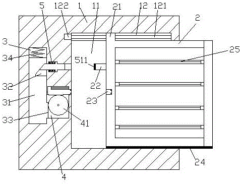
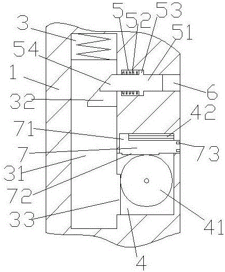
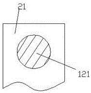
[0018] Such as Figure 1-3 As shown, a medical disinfection box device of the present invention includes a box body 1 with a sliding joint warehouse 11 inside and a drawer 2 arranged in the sliding joint warehouse 11. The front end of the drawer 2 is provided with multiple groups of A blue light tube 25, the blue light tube 25 is used for irradiation and disinfection of medical equipment, the left end of the drawer 2 is provided with an insertion shaft 22 extending to the left and an electrical connection hole 23 arranged below the insertion shaft 22 The box 1 corresponding to the inserting shaft 22 is provided with a passage 6, the left end surface of the inserting shaft 22 is provided with a round cushion portion 511, and the right end surface of the circular cushion portion 511 is in contact with the inserting shaft 22. The areas of the left end surfaces are equal, the round pad portion 511 is connected to the insertion shaft 22, and the box body 1 below the channel 6 is pr...


PUM


Abstract

The invention discloses a novel medical disinfection tank device, which comprises a tank with an internal sliding contact cabin and a pumping cabinet arranged inside the sliding contact cabin. The front end face of the pumping cabinet is provided with multiple blue light pipes, which are used for irradiation disinfection of medical equipment. The left end face of the pumping cabinet is provided with a plug-in shaft and an electric connection hole which is arranged below the plug-in shaft. A channel is arranged inside the tank corresponding to the plug-in shaft. The left end face of the plug-in shaft is provided with a round pad part, the right end face of which has the same area as the left end face of the plug-in shaft. The round pad part and the plug-in shaft are in fit connection. A rotary cabin is arranged inside the tank below the channel. A slide cabin is arranged inside the tank at the left side of the channel and the rotary cabin. A sliding table is arranged inside the slide cabin. The top of the sliding table is provided with an extensible member A. The right end face of the sliding table is equipped with a roof-contacting groove. A tooth bar A is arranged on the sliding table below the roof-contacting groove. A tooth disk is arranged inside the rotary cabin. The tooth disk is connected to the tooth bar A. A straight bar is arranged on the tooth disk. A floating block is arranged on the straight bar. The bottom of the floating block is connected to a distribution member. According to the invention, pumping time is simpler and more convenient, and pumping safety is raised.

Description

technical field [0001] The invention relates to the technical field of medical equipment, in particular to a medical disinfection box device. Background technique [0002] At present, medical disinfection boxes are widely used in the medical field. Medical disinfection boxes mainly sterilize medical instruments by irradiating blue light. Pick and place, the medical disinfection box in the prior art usually cannot cut off the power automatically when the drawer is pulled out, and it is often done manually. Frequent manual power off is not only cumbersome to operate but also likely to cause hidden dangers in operation, and there are also more operations The personnel take out the medical device without power off, which causes the blue light to directly irradiate the human skin, causing great damage to the skin. Therefore, power off when the drawer is drawn out is an important guarantee for safe operation. Contents of the invention [0003] The technical problem to be solved...

Claims


Application Information

Patent Timeline
Patent Type & Authority Applications(China)
IPC IPC(8): A61L2/08A61L2/26
CPCA61L2/084A61L2/26A61L2202/24
Inventor 不公告发明人
Owner 广州爵诺医疗器械有限公司
Why Eureka
Try Eureka