Eureka AIR delivers breakthrough ideas for toughest innovation challenges, trusted by R&D personnel around the world.

Chipless cutting device

A cutting device and cutter head technology, which is applied in the field of mechanical processing, can solve the problems of high processing cost, easy damage of sliding sleeve and push rod, high processing accuracy requirements, etc., and achieve the effect of reducing maintenance cost, reducing processing difficulty and improving stability

Active Publication Date: 2017-12-05
ZHONGSHAN CLG AUTOMATION EQUIP
View PDF7 Cites 1 Cited by
  • Summary
  • Abstract
  • Description
  • Claims
  • Application Information

AI Technical Summary

Problems solved by technology

This will lead to an unbalanced force in the cooperation between the sliding sleeve and the push rod, resulting in a stuck phenomenon in the movement of the cutter head mechanism and reducing the quality of the pipe cutting process.
The linear contact between the sliding sleeve and the push rod requires high machining accuracy, and the unbalanced force of the cooperation will easily damage the sliding sleeve and the push rod, and the processing cost is high

Method used


Image

  • Chipless cutting device
  • Chipless cutting device
  • Chipless cutting device

Examples


Embodiment Construction

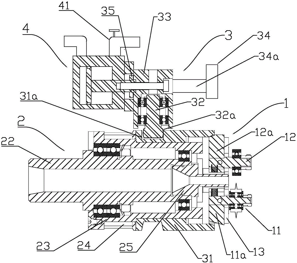
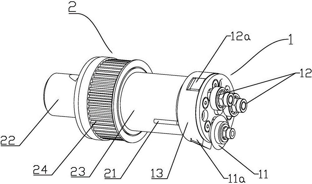
[0028] refer to Figure 1 ~ Figure 3 , The present invention is a chipless cutting device.

[0029] A chipless cutting device, comprising:

[0030] A cutter head mechanism 1, the cutter head mechanism 1 is provided with a cutter head 11 for cutting off;

[0031] A rotating mechanism 2, the rotating mechanism 2 is drivingly connected to the cutter head mechanism 1;

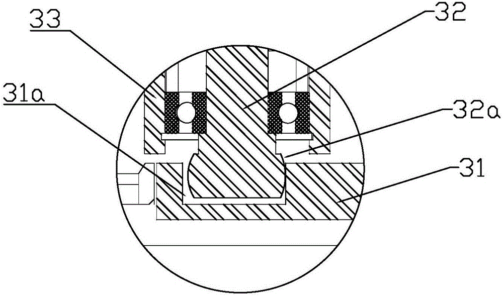
[0032] A feed mechanism 3, which includes a push rod 32 and a sliding sleeve 31;

[0033] The sliding sleeve 31 is movably fitted on the rotating mechanism 2 to drive the moving cutter head 11 to feed;

[0034] A constraining structure is provided between the push rod 32 and the sliding sleeve 31 , the constraining structure controls the relative movement of the push rod 32 and the sliding sleeve 31 along the direction of the rotation axis, and the constraining structure is a point contact constraint.

[0035] Since the cutter head mechanism 1 is in rotational motion during operation, the sliding sleeve 31 must...


PUM


Abstract

The invention discloses a chipless cutting device and relates to the field of machining. In the prior art, a chipless cutting machine comprises a cutter head mechanism, a rotating mechanism and a feeding mechanism; feeding movement transmission of the feeding mechanism is achieved through linear contact of a sliding sleeve and a push rod; and the sliding sleeve rotates passively along with the rotating mechanism, so that the linear speeds of the points, at the short distance from the rotating axis, of the sliding sleeve are low, and the linear speeds of the points, at the long distance from the rotating axis, of the sliding sleeve are high, and consequently matching stress between the sliding sleeve and the push rod is unbalanced. According to the chipless cutting device, a constraint structure is arranged between a push rod and a sliding sleeve, the constraint structure controls relative movement of the push rod and the sliding sleeve in the rotating axis direction, wherein the constraint structure adopts point contact constraint; and thus, the stress of the push rod and the sliding sleeve is balanced, the transmission stability of a feeding mechanism is improved, machining difficulty in production of the push rod and the sliding sleeve is reduced, the maintenance cost of the push rod and the sliding sleeve is reduced, and the quality of cut-off machining of pipes is improved.

Description

technical field [0001] The invention relates to the field of machining, in particular to a chipless cutting device. Background technique [0002] The production of pipe fittings involves many processes. Before the implementation of these processes, it is necessary to cut the pipe material, that is, to pre-process the raw pipe material such as straightening and cutting to length. [0003] In the prior art, the cut-to-length of the pipe adopts the chipless cutting processing method. The chipless cutting machine includes a cutter head mechanism, a rotating mechanism and a feeding mechanism. The chipless cutting machine cuts the pipe by rotating and rolling the blade of the cutter head mechanism around the outer surface of the pipe and feeding movement perpendicular to the axis of the pipe. The feeding mechanism for realizing blade feeding includes a sliding sleeve fitted outside the rotating mechanism and a push rod installed above the sliding sleeve. The push rod drives the ...

Claims


Application Information

Patent Timeline
Patent Type & Authority Applications(China)
IPC IPC(8): B23D21/04B23D33/02
CPCB23D21/04B23D33/02Y02P70/10
Inventor 董波朱必成刘忠廖亮武黄伟顺
Owner ZHONGSHAN CLG AUTOMATION EQUIP
Why Eureka
Eureka Blog
Learn More