
Rotation clamping fixture

A clamping and fixture technology, which is applied in the direction of grinding workpiece supports, etc., can solve problems such as failure to meet product appearance quality requirements, poor product processing consistency, and inability to be flexible, so as to avoid product scratches, improve processing quality, and reduce The effect of hand grip strength

Pending Publication Date: 2017-12-05
GEER TECH CO LTD
View PDF0 Cites 0 Cited by
  • Summary
  • Abstract
  • Description
  • Claims
  • Application Information

AI Technical Summary

Problems solved by technology

Due to the excessive corners of these shell products, and because the mechanical processing is too rigid, it cannot be flexible, which leads to processing dead corners in some parts of the product, especially some small corners that cannot be processed. The processing consistency is poor, the processing quality is poor, and the appearance quality requirements of the product cannot be met

Method used


Image

  • Rotation clamping fixture
  • Rotation clamping fixture
  • Rotation clamping fixture

Examples


Embodiment Construction

[0024] Below in conjunction with accompanying drawing and embodiment, further elaborate the present invention.

[0025] The orientations involved in this specification are all subject to the orientations shown in the drawings, which only represent relative positional relationships, not absolute positional relationships.

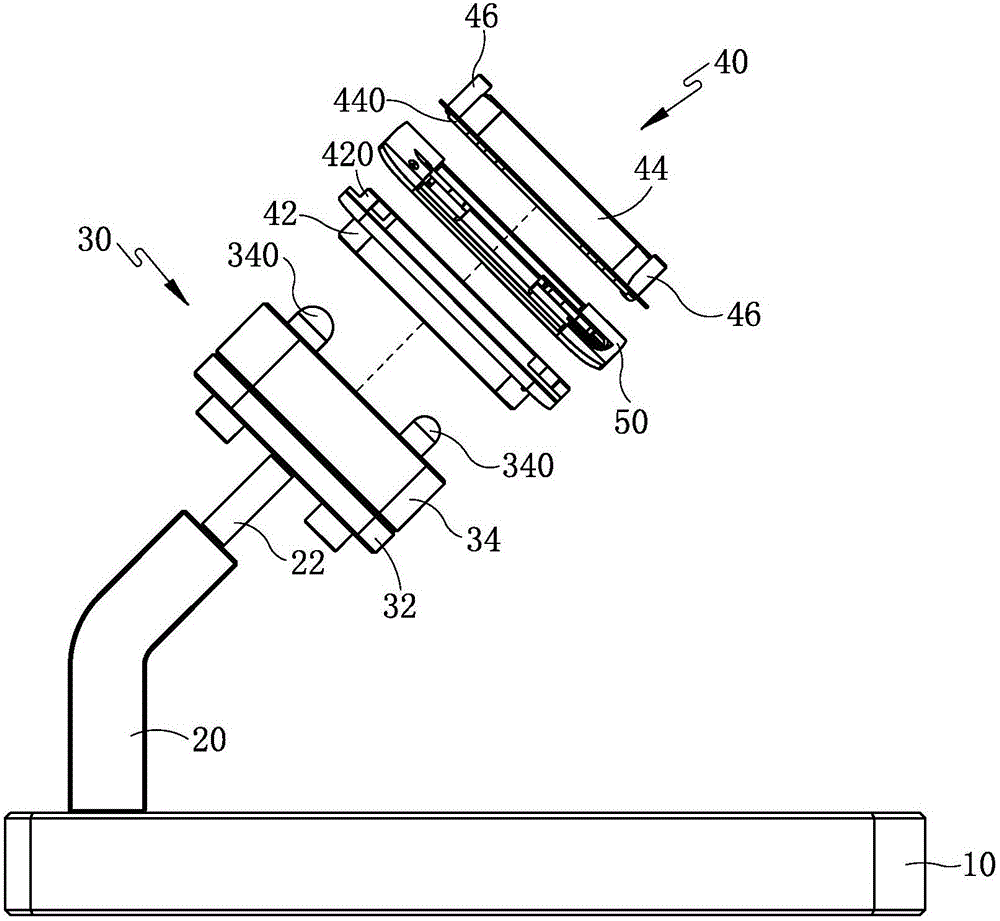
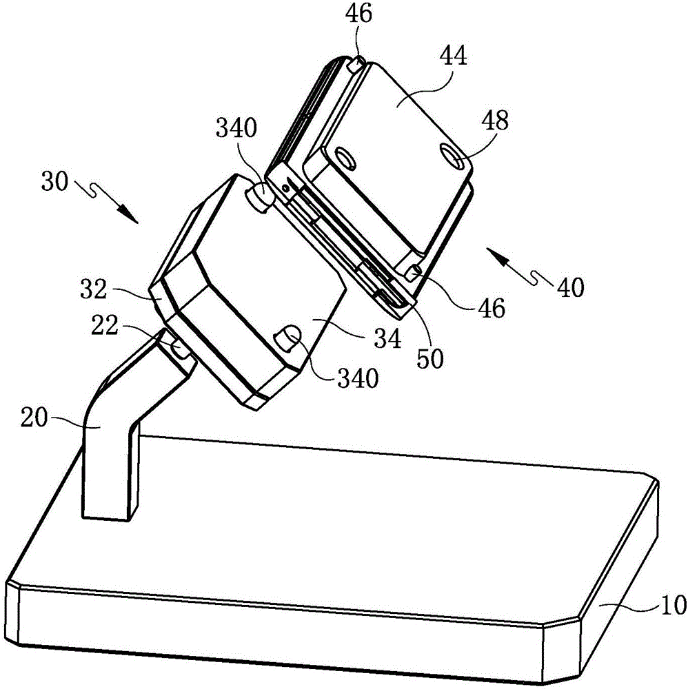
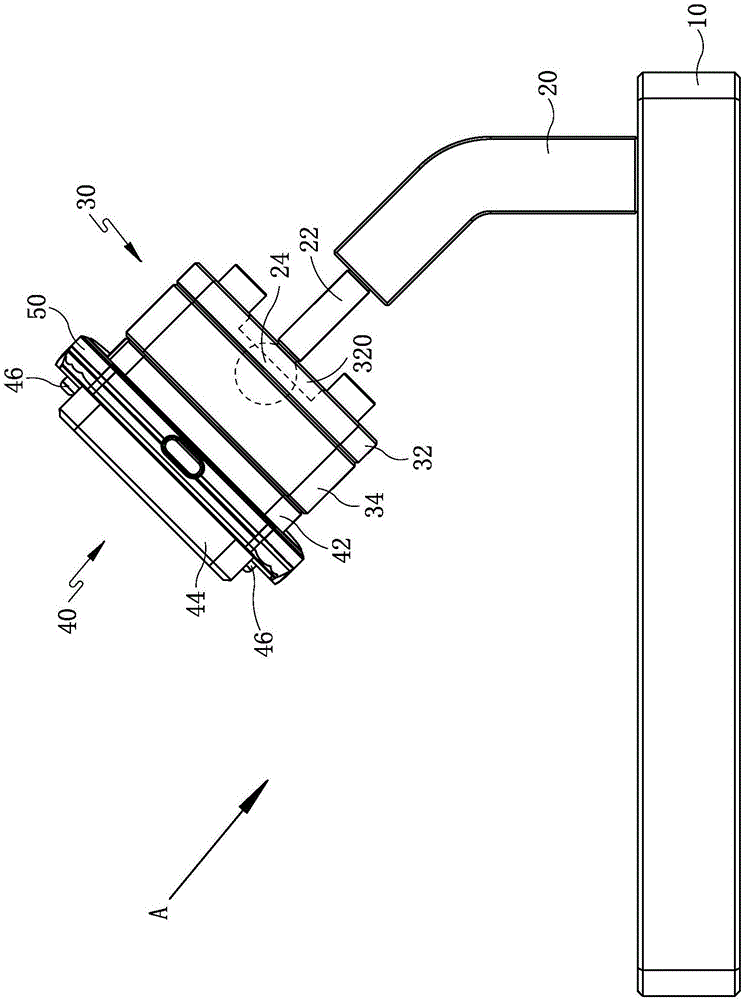
[0026] Such as figure 1 with image 3 Commonly shown, a rotary clamping fixture includes a base 10, a ball head 24 is installed on the base 10, a rotating seat 30 is installed on the ball head 24, and the rotating seat 30 can rotate around the ball head 24 in a circle of 360°, A clamping tool 40 for clamping a product 50 is detachably installed on the rotating base 30 .

[0027] Such as figure 1 , figure 2 with Figure 4 Commonly shown, in this embodiment, the swivel seat 30 is provided with a positioning pin 340, and the position corresponding to the positioning pin 340 on the clamping tool 40 is provided with a positioning pin hole 48 that is compatib...


PUM


Abstract

The invention discloses a rotation clamping fixture and relates to the technical field of metal product processing equipment. The rotation clamping fixture comprises a base and is characterized in that a ball head is mounted on the base, a rotary seat is rotatably mounted on the ball head, and the rotary seat can rotate 360 degrees around the ball head; a clamping tool for clamping a product is detachably mounted on the rotary seat. The rotation clamping fixture has the advantages that the technical problem that 360-degree dead-angle-free product processing cannot be achieved in the prior art is solved; 360-degree dead-angle-free circumferential product processing is achieved, product consistency and yield are increased, and the rotation clamping fixture is high in production efficiency, simple in structure and low in cost.

Description

technical field [0001] The invention relates to the technical field of metal product processing equipment, in particular to a product clamping jig capable of rotating a product in a 360° circle. Background technique [0002] The mechanical processing of metal products usually requires multiple processes, such as machining in the previous process, and polishing, wire drawing, sandblasting and deburring in the post-process. Some shell metal products need to be polished, brushed and deburred all around during processing, such as watch shells or mobile phone shells. Due to the excessive corners of these shell products, and because the mechanical processing is too rigid, it cannot be flexible, which leads to processing dead corners in some parts of the product, especially some small corners that cannot be processed. The processing consistency is poor, the processing quality is poor, and the appearance quality requirements of the product cannot be met. Contents of the invention...

Claims


Application Information

Patent Timeline
IPC IPC(8): B24B41/06
CPCB24B41/06
Inventor 程宝回燕华程品
Owner GEER TECH CO LTD
Learn More