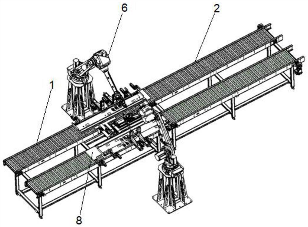
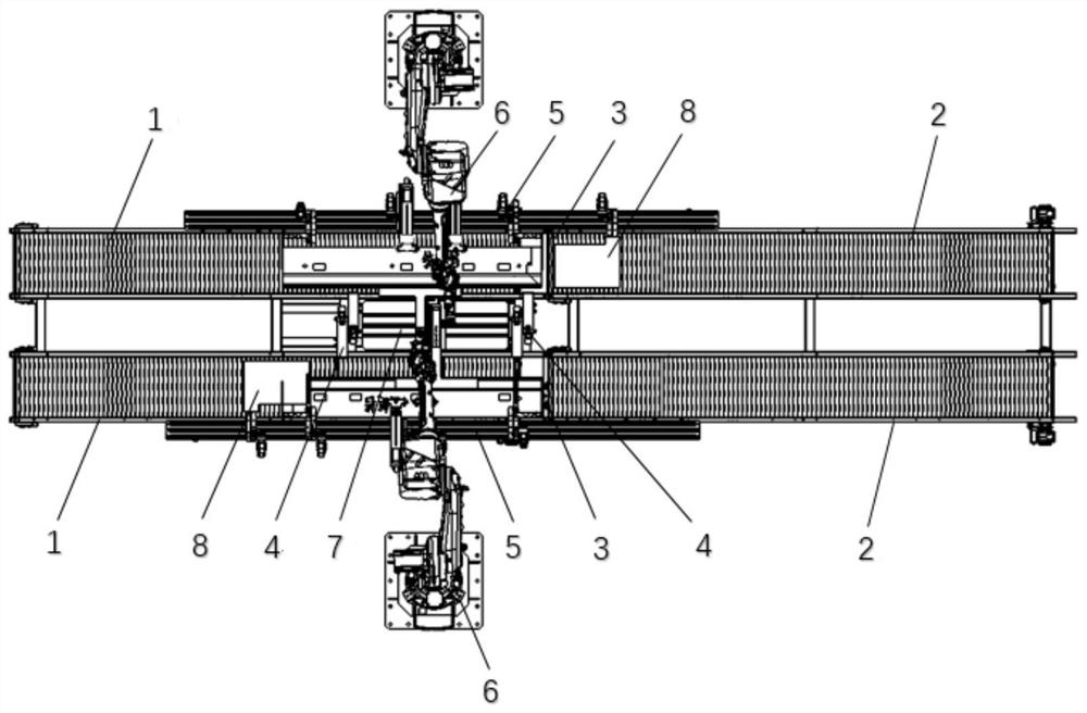
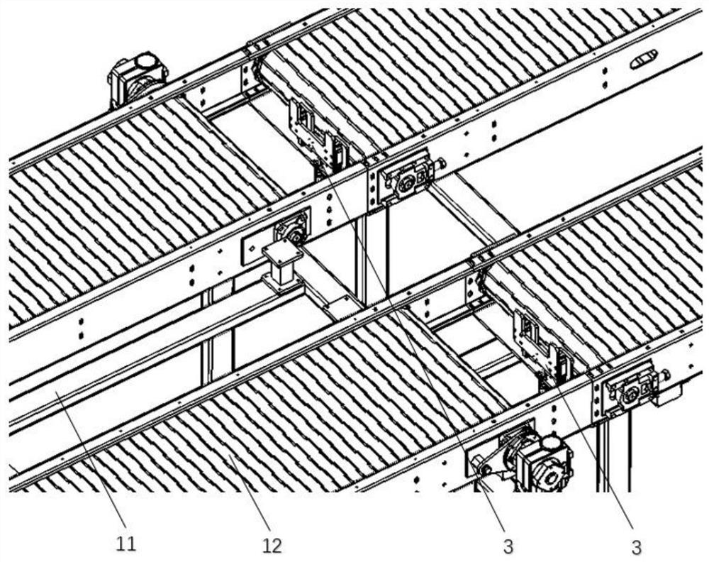
Automatic cutting device compatible with various hinge door stop plates

A cutting device, door panel technology, applied in welding equipment, laser welding equipment, metal processing equipment, etc., can solve the problem that the operation grasping method is difficult to achieve X, Y, Z axis movement, inconvenient to set laser cutting protection mechanism, and the robot does not work. It can realize problems such as free movement, achieve good practical performance and promotion value, reduce workload, and ensure the effect of processing consistency

Pending Publication Date: 2020-09-29
上海电气自动化集团有限公司
View PDF0 Cites 2 Cited by
  • Summary
  • Abstract
  • Description
  • Claims
  • Application Information

AI Technical Summary

Problems solved by technology

When cutting circular or elliptical holes, the robot needs to ensure that the laser is always perpendicular to the working surface and every point of the laser cutting track to ensure that the cut shape is a standard circular or elliptical shape, and the 45° inclined positioning method is adopted. , it is difficult to guarantee the processing quality. In order to achieve the cutting effect, the debugging personnel need to carry out a lot of debugging work, which reduces the production efficiency.
At the same time, with the 45° inclined positioning method, it is difficult to move the X, Y, and Z axes in the grasping method, and the robot cannot move freely in the plane cutting, which affects the processing efficiency
For the 90° positioning method, the laser cutting light is facing the direction of the person, and there is a certain safety risk
The above two positioning methods are not convenient to set up a laser cutting protection mechanism, and there is a possibility that the laser beam of the laser will damage other parts during the cutting process, which will affect the performance of the equipment

Method used


Image

  • Automatic cutting device compatible with various hinge door stop plates
  • Automatic cutting device compatible with various hinge door stop plates
  • Automatic cutting device compatible with various hinge door stop plates

Examples


Embodiment Construction

[0037] In order to make the technical problems solved by the present invention, the technical solutions adopted and the technical effects achieved clearer, the technical solutions of the embodiments of the present invention will be further described in detail below in conjunction with the accompanying drawings. Obviously, the described embodiments are only the technical solutions of the present invention. Some, but not all, embodiments. Based on the embodiments of the present invention, all other embodiments obtained by those skilled in the art without creative efforts fall within the protection scope of the present invention.

[0038] In the description of the present invention, unless otherwise clearly stipulated and limited, the terms "connected", "connected" and "fixed" should be understood in a broad sense, for example, it can be a fixed connection, a detachable connection, or an integral body; It can be a mechanical connection or an electrical connection; it can be a dir...


PUM


Abstract

The invention relates to the technical field of automatic laser cutting of non-standard hinge stop door plates, and discloses an automatic cutting device compatible with various hinge stop door plates. The automatic cutting device compatible with the various hinge stop door plates comprises a first section of chain transmission assembly, a second section of chain transmission assembly, a stop assembly, a side thrust servo assembly, a positioning and clamping assembly, a robot assembly, a first protection assembly and a second protection assembly. According to the automatic cutting device compatible with the various hinge stop door plates, completely positioning a to-be-machined product can be carried out through the side thrust servo assembly and the positioning and clamping assembly, so that the machining consistency of the to-be-machined product can be effectively guaranteed; meanwhile, a suction assembly can move in an X axis, a Y axis and a Z axis, so that free movement of the robot assembly in plane cutting can be achieved, and the cutting efficiency is improved; and compared with a 45-degree or 90-degree positioning to-be-machined product laser cutting mode or a manual machining mode in the prior art, the equipment safety performance and reliability are improved, the two hands of an operator are liberated, the workload is relieved, time and labor are saved, and thereforethe production cost is reduced, and the production efficiency is improved.

Description

technical field [0001] The invention relates to the technical field of laser cutting of non-standard hinged door panels, in particular to an automatic cutting device compatible with various hinged door panels. Background technique [0002] With the steady and rapid development of China's economy, infrastructure construction, urban village transformation, shantytown transformation, old village transformation and new rural construction are being implemented all over the country. , A large number of commercial houses are gradually pouring into the market. At the same time, with the opening of the country, the volume of import and export commodities is also increasing. Therefore, the demand for the door is increasing. However, with the continuous improvement of people's living standards, the quality requirements for doors are also getting higher and higher. At present, domestic door manufacturing enterprises still use a large number of traditional manufacturing methods, using m...

Claims


Application Information

Patent Timeline
Patent Type & Authority Applications(China)
IPC IPC(8): B23K26/38B23K26/08B23K26/70
CPCB23K26/0884B23K26/38B23K26/702
Inventor 方进任跃森肖高李毅郭东波
Owner 上海电气自动化集团有限公司
Why Eureka
Try Eureka