Modular orthorgonal-structured snake robot

A snake-shaped robot, modular technology, applied in the field of robot research and engineering, can solve problems such as non-smooth contact, contact with the surrounding environment, damage, etc., achieve the effect of compact and small shape, expand the range of activities, and avoid stuck effects

Inactive Publication Date: 2017-12-05
SUN YAT SEN UNIV
View PDF6 Cites 1 Cited by
  • Summary
  • Abstract
  • Description
  • Claims
  • Application Information

AI Technical Summary

Problems solved by technology

Each joint mainly includes a servo controller, a movable plate, and a connecting plate. This structure just meets the activity needs of each joint and is not suitable for high-intensity sports; and the joint structure is in the shape of a cuboid. and the surrounding environment cannot be in smooth contact
[0006] 2. Some components are exposed and easily damaged
Due to the relatively simple design of the joint structure and the lack of shell protection, the connection lines between the joints are exposed, and in strong motion scenarios, it is easy to contact the surrounding environment and cause damage
[0007] 3. Relatively low power
[0008] 4. The stability of the communication system is relatively insufficient
The patented sensor is relatively simple and has insufficient awareness of the surrounding environment

Method used


Image

  • Modular orthorgonal-structured snake robot
  • Modular orthorgonal-structured snake robot
  • Modular orthorgonal-structured snake robot

Examples


Embodiment 1

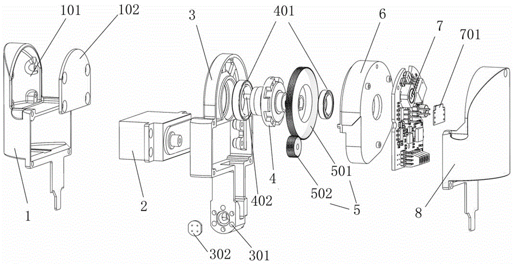
[0032] Example 1: as figure 1 As shown, the upper end of the main frame 3 of the single joint of the present invention and the bearing cover 6 are provided with through holes, the through holes are provided with bearings 401, one end of the output shaft 4 is installed in the bearing on the upper end of the main frame 3, and the other end passes through the deceleration The large tooth 501 on the device 5 is installed in the bearing on the bearing cover plate 6 . The bearing end cover 6 is connected to the main frame 3 , and the bearing 401 , the output shaft 4 and the reducer 5 are enclosed in the main frame 3 , the control system 7 is installed on the bearing end cover 6 , and the sensor system 701 is electrically connected to the control system 7 . The motor 2 is installed in the middle of the main frame 3, the motor 2 is connected with the small teeth 502, the motor 2 is placed in the hollow position of the lower end of the lower cover 1, the upper end of the lower cover 1 ...

Embodiment 2

[0040] Embodiment 2: This embodiment is similar to Embodiment 1, the difference is that the communication system adopts the CAN bus protocol to design the control system, and the communication structure of this system is adopted to improve the low communication efficiency existing in the original ordinary communication system, and the resistance to resistance is low. Poor interference ability, easy to crash and unstable.

Embodiment 3

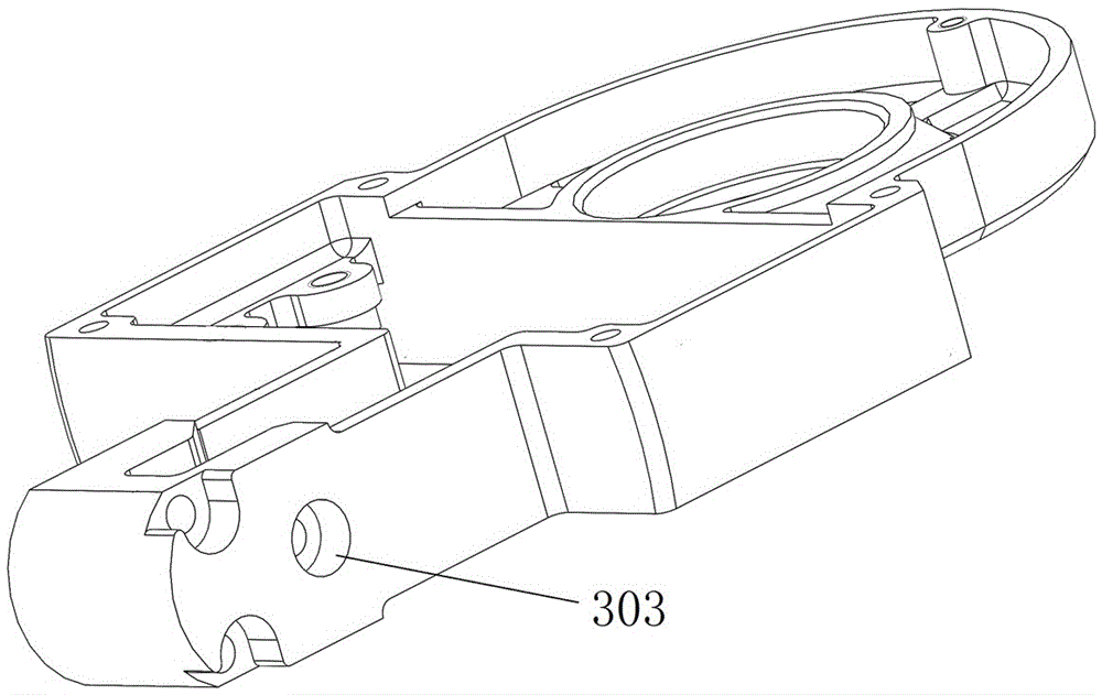
[0041] Embodiment 3: This embodiment is similar to Embodiment 2, except that, as image 3 As shown, the screw holes 303 at the lower end of the main frame for fixing the adjacent two joint modules are countersunk, and the screw heads are buried under the surface of the main frame 3, so that the main frame 3 and the lower cover of the upper section stabilize the compartment The cover plate is kept flat with no protrusions relative to the plane to prevent interference between them.


PUM


Abstract

The invention relates to the field of robot research and engineering, particularly to a modular orthorgonal-structured snake robot. The modular orthorgonal-structured snake robot is composed of a plurality of joint modules; the inside of every joint module is provided with a driving system and a control system, and the joint modules are connected end to end in a 90-degree relative rotation mode; every control system is electrically connected with the corresponding driving system, and the neighboring joint modules are driven to rotate by the corresponding driving systems. By means of modular joints, joint strength and reliability can be enhanced; by means of a cylindrical case and a stable transmission system, high-strength operation can be ensured; powered by a steering engine, the snake robot can ensure integral power output; the outer cylindrical case is made of light materials to ensure smooth contact with the snake robot and the surroundings and meanwhile to package the internal parts of joints to avoid damage due to exposure.

Description

technical field [0001] The invention relates to the field of robot research and engineering, and more particularly, to a snake-shaped robot with a modular orthogonal structure. Background technique [0002] Authorization Announcement No.: CN1251841C, discloses a modular variable-structure snake-shaped robot, which consists of multiple joint modules with the same structure and a single degree of freedom. Each joint module has a servo controller, a movable plate, and a connecting plate. The joint modules are connected in turn through the movable plate and the connecting plate, and the snake body structure is formed by the connection mode in which the direction difference of the adjacent joint modules is 0 and / or 90 degrees, and the servo controller of each joint module is respectively connected with the control board, and then with The control program signals in the main control computer are communicated. According to the requirements of the application background, the invent...

Claims


Application Information

Patent Timeline
Patent Type & Authority Applications(China)
IPC IPC(8): B25J9/06
CPCB25J9/065
Inventor 黄凯管卓群程龙邴振山
Owner SUN YAT SEN UNIV
Why Eureka
Try Eureka