Runner crown structure of rotating wheel of water turbine

A crown-on-wheel and water-turbine technology, which is applied in hydroelectric power generation, mechanical equipment, machines/engines, etc., can solve the problems of insufficient transitional arcs and large changes in thickness, and achieve guaranteed use effects, reasonable structure, and convenient and reliable use. Effect

Inactive Publication Date: 2017-12-05
DEQING DONGXU ALLOY STEEL CASTING
View PDF3 Cites 0 Cited by
  • Summary
  • Abstract
  • Description
  • Claims
  • Application Information

AI Technical Summary

Problems solved by technology

[0002] The runner of the water turbine is usually welded by the upper crown, the lower ring and the blades. After welding, a large welding residual stress will be generated. In order to ensure the safety of the runner during operation, it will not be generated due to excessive residual stress. Deformation and cracking, it is necessary to eliminate welding residual stress. In addition, how to overcome the shortcomings of the runner structure, such as the rationality of the structure, can also reduce or reduce the deformation stress caused by welding. Due to the existing runner, In particular, the upper crown structure of the runner is still unreasonable, such as large thickness changes, insufficient transition arcs, etc., so it is urgent to propose reasonable improvements in the structure

Method used


Image

  • Runner crown structure of rotating wheel of water turbine

Examples


Embodiment Construction

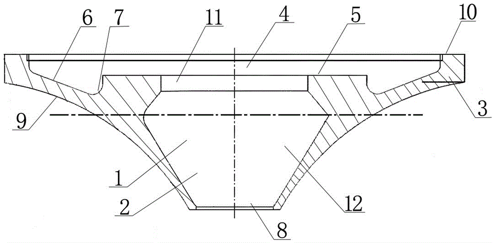
[0008] The present invention will be described in detail below in conjunction with accompanying drawing: figure 1 As shown, the crown structure of a water turbine runner according to the present invention includes a wheel-shaped crown body 2 with an axial through hole 1 in the middle, and the large-diameter wheel disc 3 of the crown body 2 is located at The upper end side, the upper surface of the upper end side is provided with a recessed special-shaped ring groove 4, wherein: a downwardly recessed platform surface 5 is arranged in the middle, an axial through hole 11 is formed in the middle of the upper end, and an oblique groove is formed on the periphery of the platform surface 5. An annular groove 6 on the bottom surface, and a circular arc transition 7 is formed on the inner and outer ends of the annular groove 6; the lower end of the axial through hole 11 of the upper end is connected with a thick waist-shaped through hole 12 in the middle until the lower end of the uppe...


PUM


Abstract

A runner crown structure of a rotating wheel of a water turbine comprises a wheel disc type runner crown body, wherein an axial through hole is formed in the middle of the wheel disc type runner crown body. A large-diameter wheel disc of the runner crown body is located on an upper end edge. A sunken special-shaped ring groove is inward formed in the upper face of the upper end edge. A downward-sunken platform face is arranged in the middle of the special-shaped ring groove, an upper end axial through hole is formed in the middle of the platform face, an annular groove with the inclined bottom face is formed in the periphery of the platform face, and arc transition parts are formed in the inner end edge and the outer end edge of the annular groove. The lower portion of the upper end axial through hole is connected with a lower end edge, wherein a thick-kidney-shaped through hole is formed from the middle of the lower end edge to the upper runner crown body. The lower end edge of the upper runner crown body is a small-diameter end edge opening. An inner arc-shaped inclined circumferential wall is formed between the outer wall of the small-diameter end edge opening and the bottom of the large-diameter wheel disc. The upper end face of the large-diameter wheel disc is a positioning annular flat end face. The diameter of the upper end axial through hole is larger than the inner diameter of the small-diameter end edge opening. The runner crown structure has the characteristics that the structure is reasonable, using is convenient and reliable, welding strength is enough, and the using effect of the rotating wheel is guaranteed.

Description

technical field [0001] The invention relates to a crown structure for a runner of a hydraulic turbine, which belongs to the technical field of hydraulic turbines for hydroelectric power generation equipment. Background technique [0002] The runner of the water turbine is usually welded by the upper crown, the lower ring and the blades. After welding, a large welding residual stress will be generated. In order to ensure the safety of the runner during operation, it will not be generated due to excessive residual stress. Deformation and cracking, it is necessary to eliminate welding residual stress. In addition, how to overcome the shortcomings of the runner structure, such as the rationality of the structure, can also reduce or reduce the deformation stress caused by welding. Due to the existing runner, In particular, the upper crown structure of the runner still has unreasonable problems, such as large thickness changes, insufficient transition arcs, etc., so it is urgent t...

Claims


Application Information

Patent Timeline
Patent Type & Authority Applications(China)
IPC IPC(8): F03B3/12
CPCF03B3/12Y02E10/20
Inventor 梅学汉张贤杰
Owner DEQING DONGXU ALLOY STEEL CASTING
Why Eureka
Try Eureka