Compressor pump body, compressor and assembly method of compressor pump body

A compressor pump and assembly method technology, which is applied in the field of compressors, can solve the problems of large friction power consumption and large impact on compressor performance, and achieve the effects of reducing friction power consumption, reducing relative motion linear velocity, and improving performance

Active Publication Date: 2017-12-05
ZHUHAI GREE REFRIGERATION TECH CENT OF ENERGY SAVING & ENVIRONMENTAL PROTECTION
View PDF4 Cites 1 Cited by
  • Summary
  • Abstract
  • Description
  • Claims
  • Application Information

AI Technical Summary

Problems solved by technology

[0004] However, the inventors of the present invention found that the above-mentioned improvement scheme has the following technical problems: the slider is in direct contact with the cylinder, and during the operation of the compressor, the outer circle of the slider and the The inner circle of t

Method used


Image

  • Compressor pump body, compressor and assembly method of compressor pump body
  • Compressor pump body, compressor and assembly method of compressor pump body
  • Compressor pump body, compressor and assembly method of compressor pump body

Examples


Embodiment 1

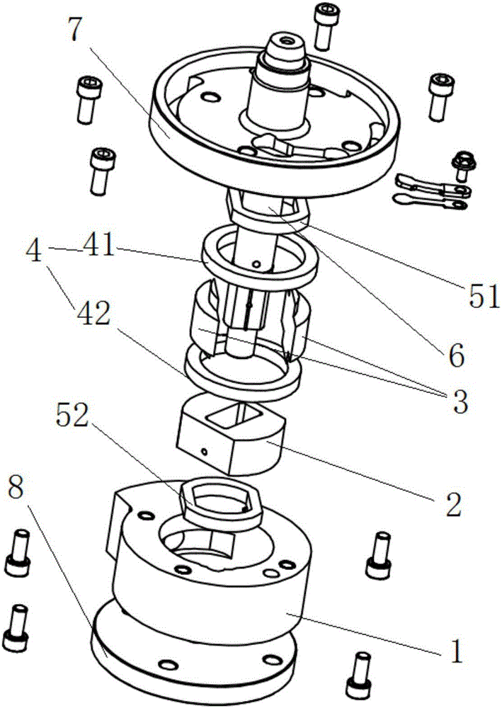
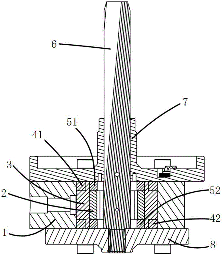
[0061] This embodiment provides a compressor pump body, such as figure 1 and figure 2 As shown, the pump body of the compressor in this embodiment includes a cylinder 1 , a piston 2 , a slider 3 and a limiting structure 4 . Wherein, the piston 2 is movably installed in the cylinder 1, and the outer circumference of the piston 2 includes a first plane and a first arc surface. A slider 3 is installed between the first plane of the piston 2 and the inner surface of the cylinder 1 ; the first arc surface of the piston 2 is adapted to the inner surface of the cylinder 1 . Wherein, the outer circumference of the slider 3 includes a second plane and a second arc surface, and the second plane on the slider 3 cooperates with the first plane on the piston 2 to ensure that the piston 2 can operate normally in the cylinder; and the slider The second arc on the 3 is adapted to the inner surface of the cylinder 1. The limiting structure is connected with the slider 3 and is used for li...

Embodiment 2

[0066] Preferably, this embodiment provides a compressor pump body. Compared with the previous embodiment, this embodiment further designs the limiting structure as follows:

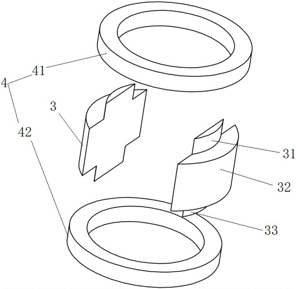
[0067] Such as Figure 2 to Figure 6 As shown, the limiting structure in this embodiment includes a limiting collar 4 . Wherein, the limiting collar 4 is located in the cylinder 1 , and all the sliders 3 are sheathed in the limiting collar 4 together. Here, in this embodiment, the limiting structure is set as the limiting collar 4, so that all the sliders 3 are sleeved in the limiting collar 4 together, so that the limiting collar 4 can limit the sliders. position, so as to prevent the slider 3 from moving outwards (toward the inner surface of the cylinder) when the compressor is working, so as to prevent the outer circular surface (the second arc surface) of the slider 3 from contacting the inner surface of the cylinder 1, thereby reducing the corresponding Friction power consumption.

[0068] Here, ...

Embodiment 3

[0073] Preferably, this embodiment provides a compressor pump body, compared with Embodiment 2, such as Figure 1 to Figure 4 and Figure 6 As shown, there are two limiting collars 4 in this embodiment, that is, the first limiting collar 41 and the second limiting collar 42; wherein, the upper ends of all the sliders 3 are sleeved on the first Inside the limiting collar 41 ; the lower ends of all the sliders 3 are sheathed in the second limiting collar 42 together.

[0074] In this embodiment, two spacer collars are provided to limit the upper end and the lower end of the slider 3 at the same time, so that the stability of the position limitation is better, and the contact between the slider 3 and the inner surface of the cylinder 1 can be further avoided, and further Reduce the frictional power consumption between the slider 3 and the cylinder 1, and reduce the frictional power consumption of the compressor to improve the performance of the compressor.

[0075] Preferably, ...


PUM


Abstract

The invention provides a compressor pump body, a compressor and an assembly method of the compressor pump body and relates to the technical field of compressors. According to the main technical scheme, the compressor pump body comprises an air cylinder, a piston, a sliding block and a limiting structure, wherein the piston is mounted in the air cylinder, and the periphery of the piston comprises a first plane; the sliding block is mounted between the first plane of the piston and the inner surface of the air cylinder; the periphery of the sliding block comprises a second plane and a second cambered surface, wherein the second plane and the first plane are in sliding fit, and the second cambered surface and the inner surface of the air cylinder are adaptive; and the limiting structure is connected with the sliding block and used for limiting the sliding block to enable a gap to exist between the sliding block and the inner surface of the air cylinder. The compressor pump body is mainly used for reducing friction power consumption between the sliding block and the air cylinder in the compressor pump body, and promoting the performance of the compressor.

Description

technical field [0001] The invention relates to the technical field of compressors, in particular to a compressor pump body, a compressor and an assembly method for the compressor pump body. Background technique [0002] In the pump body of the existing rotary cylinder piston compressor, the cylinder liner is sleeved on the cylinder and installed coaxially, and the suction and exhaust channels are all distributed on the cylinder liner. The piston is placed in the installation hole of the cylinder, wherein the piston adopts a non-circular structure, that is, the outer circular surface of the piston is an arc surface at both ends, and two parallel surfaces are distributed in the middle (two outer circular surfaces are set opposite to each other, and two parallel surfaces Relatively set); and the inner surface of the cylinder that cooperates with the piston is also made of two arc surfaces and two parallel surfaces, which leads to a complex structure of the cylinder, and the co...

Claims


Application Information

Patent Timeline
IPC IPC(8): F04C29/00F04C27/00
CPCF04C27/005F04C29/00F04C2240/20F04C2230/60
Inventor 杜忠诚杨森孔令超任丽萍徐嘉刘喜兴李直梁社兵
Owner ZHUHAI GREE REFRIGERATION TECH CENT OF ENERGY SAVING & ENVIRONMENTAL PROTECTION
Why Eureka
Try Eureka