

Sided-intake sealer of agitator
A sealing device and agitator technology, which is applied to the sealing of mixers with rotating agitating devices, mixer accessories, and engines, can solve the problems of fast packing wear, large wear power loss, inconvenient use and maintenance, etc.
- Summary
- Abstract
- Description
- Claims
- Application Information
AI Technical Summary
Problems solved by technology
Method used
Image

Examples
Embodiment Construction
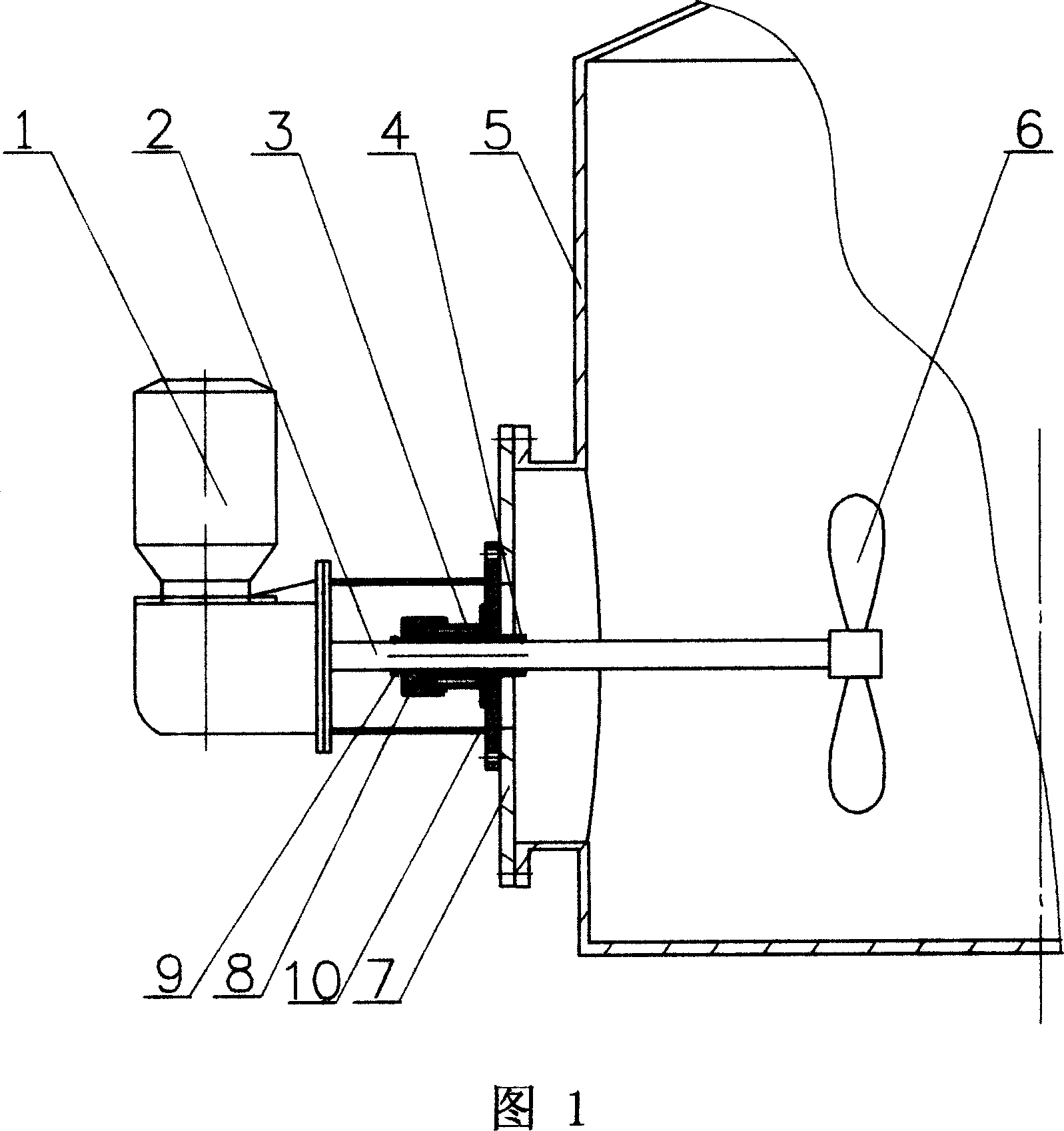
[0014] In the structure shown in Figure 1, a sealing mounting seat 10 is fixedly fixed and sealed by the agitator installation wall plate 7 at the position of the side wall installation hole of the container 5 such as the reaction tank, tank or reaction kettle, which is convenient for the installation of the agitator. For maintenance, of course, the sealing mount 10 can also be directly fixed on the side wall of the container 5 . Agitator shaft 2 passes through the inner side plate of seal mounting seat 10 and agitator installation wall plate 7, and stretches in the material liquid level of container 5. Stirring shaft 2 is equipped with stirring paddle 6 at the end of the extension, and the outer end of stirring shaft 2 is connected with stirring motor 1 to drive the stirring shaft 2 and stirring paddle 6 to rotate, so as to realize the control of the material in the container 5. Stir.
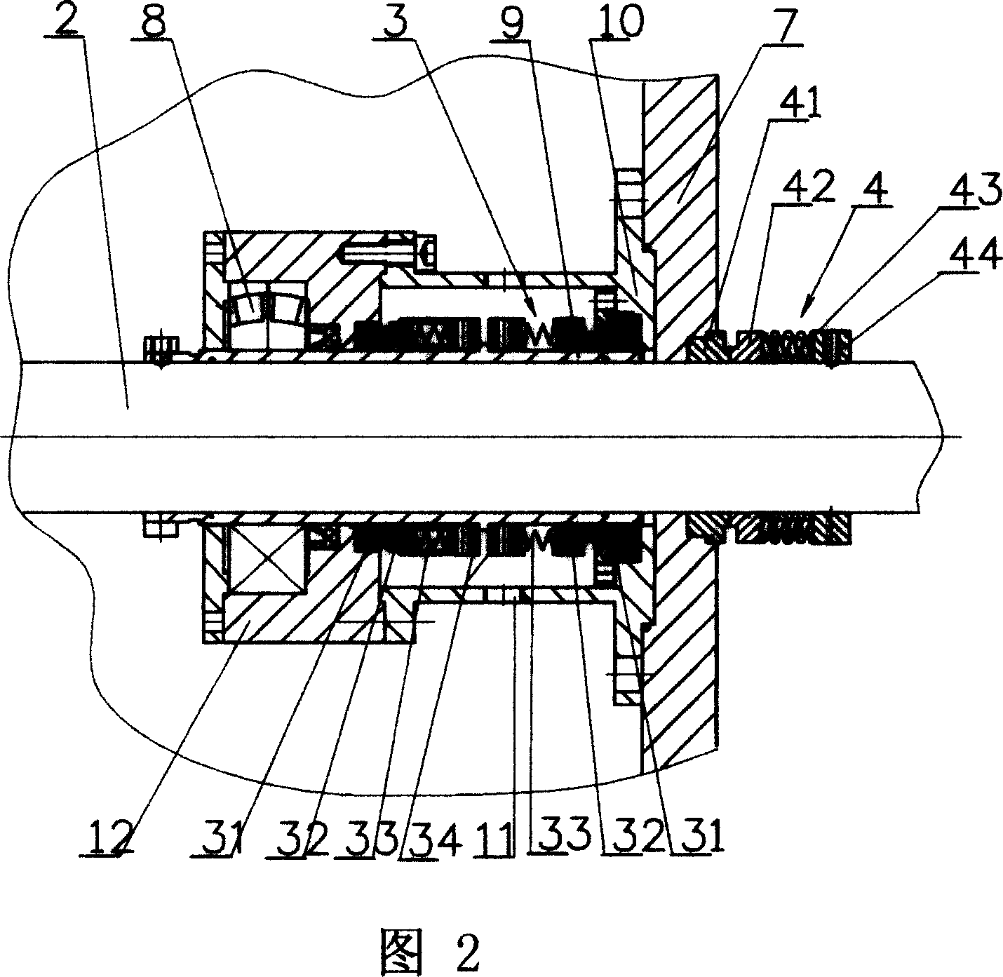
[0015] As shown in Figure 2, a side inner end mechanical seal 4 is installed between the ...
PUM
 Abstract
Description
Claims
Application Information