Automatic assembly device of check rings for shafts

An automatic assembly device and shaft retaining ring technology, which is applied in metal processing, metal processing equipment, manufacturing tools, etc., can solve the problems of high labor intensity, high cost, and time-consuming manual assembly, so as to improve the work safety factor, The effect of improving work efficiency and reducing labor costs

Pending Publication Date: 2017-12-08
WUHAN LIANHANG ELECTROMECHANICAL
View PDF12 Cites 13 Cited by
  • Summary
  • Abstract
  • Description
  • Claims
  • Application Information

AI Technical Summary

Problems solved by technology

[0005] The purpose of the present invention is to provide an automatic assembly device for shaft retaining rings, which is used to solve the problems in the prior art that manual assembly is time-consuming, low in efficiency, labor-intensive, high in cost, and prone to missing assembly

Method used


Image

  • Automatic assembly device of check rings for shafts
  • Automatic assembly device of check rings for shafts
  • Automatic assembly device of check rings for shafts

Examples


Embodiment 1

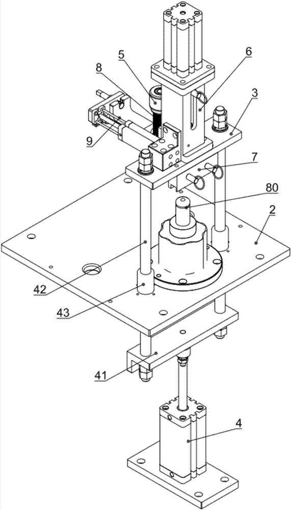
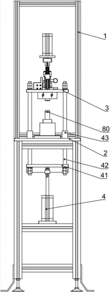
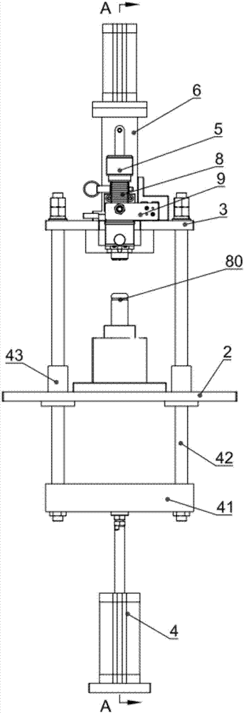
[0066] Such as Figure 1-4 and Figure 7 As shown, this embodiment provides an automatic assembly device for shaft retaining rings, such as figure 1 As shown, it includes a frame 1, and also includes a workbench 2, which is fixed on the frame 1 for placing parts to be assembled; a fixed plate 3, which is arranged above the workbench 2, and a conveying channel 31 is arranged on the fixed plate 3 ; The jacking cylinder 4 is fixed on the frame 1 and is located below the workbench 2. The extended end of the jacking cylinder 4 is connected to the fixing plate 3 for driving the fixing plate 3 to reciprocate relative to the workbench 2;

[0067] Such as Figure 5 and Figure 6 As shown, the storage unit 5 is set on the fixed plate 3, and the retaining ring 8 is set on the storage unit 5; the press-fit unit 6 is set on the fixed plate 3, and the guide unit 7 is arranged in turn below the press-fit unit 6 And retaining ring groove 80;

[0068] Such as Figure 7 and Figure 8 As ...

Embodiment 2

[0101] On the basis of the first embodiment above, the difference between this embodiment and the first embodiment is that the protruding end of the jacking cylinder 4 in the shaft retaining ring automatic assembly device in this embodiment is fixed on the workbench 2, The workbench 2 can reciprocate in a direction close to or away from the fixed plate 3 , and the fixed plate 3 , storage unit 5 , press-fit unit 6 , guide unit 7 and push unit 9 are fixed on the frame 1 .


PUM


Abstract

The invention discloses an automatic assembly device of check rings for shafts. The device comprises a rack and further comprises a workbench, a fixing plate, a lifting air cylinder, a material storage unit, a press-mounting unit, a pushing unit and a control unit; the workbench is used for containing parts to be assembled; the fixing plate is arranged above the workbench, and a conveying channel is formed in the fixing plate; the lifting air cylinder is fixed onto the rack, located below the workbench and used for driving the fixing plate and the workbench to move back and forth relatively; the material storage unit is arranged on the fixing plate, and the check rings are arranged on the material storage unit in a sleeving mode; the press-mounting unit is arranged on the fixing plate, and a guide unit and a check ring groove are formed below the press-mounting unit in sequence; the pushing unit is arranged on the fixing plate and pushes the check rings to a guide unit, and the press-mounting unit pushes the check rings of the guide unit into the check ring groove; the control unit, the material storage unit, the pushing unit and the press-mounting unit are all electrically connected to the control unit. According to the automatic assembly device, the problems are solved that in the prior art, manual assembly consumes working hours, the efficiency is low, the labor intensity of personnel is high, the cost is high, and neglected loading exists easily.

Description

technical field [0001] The invention relates to the technical field of automatic assembly, in particular to an automatic assembly device for a retaining ring for a shaft. Background technique [0002] The function of the retaining ring is to prevent axial movement of other parts assembled on the shaft, and the assembly of the retaining ring for the shaft is mostly done manually with the help of auxiliary tools. [0003] A quick assembly device for retaining ring in the present technology is used to assemble the retaining ring on the bolt journal. This device includes a guide sleeve and a push cylinder. Groove, manually install the retaining ring on the guide cone until it cannot be pushed manually; [0004] The guide sleeve is installed inside the push cylinder. When the retaining ring cannot be pushed on the guide cone, use the push cylinder to push the retaining ring away from the guide cone until the retaining ring is pushed to the other end of the guide sleeve. At -5mm...

Claims


Application Information

Patent Timeline
Patent Type & Authority Applications(China)
IPC IPC(8): B23P19/027
CPCB23P19/001B23P19/005B23P19/006B23P19/027
Inventor 毛宜升徐华杰何明汪伟魏杰
Owner WUHAN LIANHANG ELECTROMECHANICAL
Why Eureka
Try Eureka