
Paper tube shaping machine

A technology of shaping machine and paper tube, which is applied in the direction of grinding workpiece supports, grinding machines, metal processing equipment, etc., can solve the problems of low production efficiency, waste, and multiple processing, and achieve high production efficiency, reduce production costs, and slot Accurate effect

Inactive Publication Date: 2017-12-08
TONGXIANG HENGYI PAPER PLASTIC
View PDF6 Cites 1 Cited by
  • Summary
  • Abstract
  • Description
  • Claims
  • Application Information

AI Technical Summary

Problems solved by technology

The existing paper tube shaping machine is usually equipped with two sets of grinding head devices, the production efficiency is low, and a set of equipment can only produce products of one specification, and different types of equipment need to be purchased for different types of equipment, which increases the production cost; The existing paper tube shaping machine is not stable when slotting, and the paper tube will be displaced or cannot be fed and returned normally due to unstable clamping.
Due to the wear and tear of the fixture, the paper tube cannot be sent or returned in time, and the same paper tube will be processed many times, and the stable clamping function will also be lost, and the slotting of the paper tube will fail. Irregularity will affect the quality of the product and cause the paper tube to be scrapped
As the final process of paper tube production, a large number of scraps greatly reduces production efficiency, causes a lot of waste, increases production costs, cannot guarantee stable production, and increases the labor intensity of maintenance personnel.

Method used


Image

  • Paper tube shaping machine
  • Paper tube shaping machine
  • Paper tube shaping machine

Examples


Embodiment Construction

[0016] The specific embodiment of the present invention will be described in detail below in conjunction with accompanying drawing, the advantage of the present invention and outstanding contribution relative to prior art are further set forth, it can be understood that the following examples are only detailed descriptions of preferred embodiments of the present invention , should not be construed as any limitation on the technical solution of the present invention.

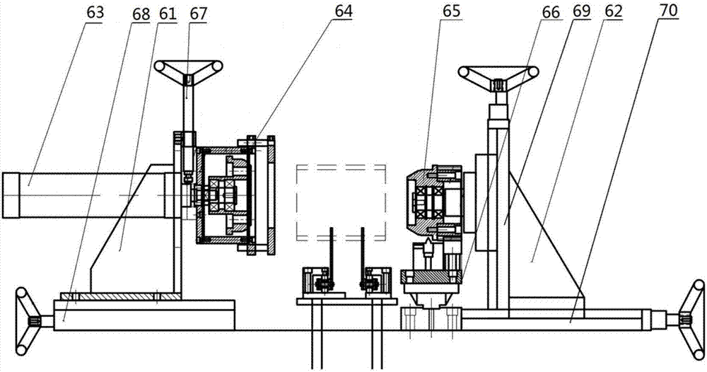
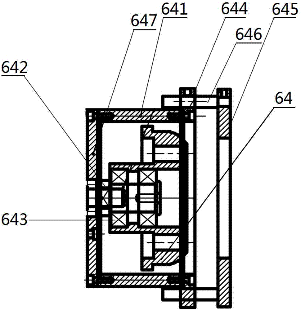
[0017] Such as Figure 1-4 As shown, a paper tube shaping machine includes a frame 1, and the middle part of the upper end of the frame 1 is provided with a conveying device 2. The belt 21 and the drive motor 22 that drives the conveyor belt 21 to rotate, the upper end of the frame 1 is provided with a feeding device 3, a grinding head device 4, a polishing device 5 and an opening device in sequence from left to right along the two sides of the conveyor belt 22. Groove device 6, three sets of grinding head devic...


PUM


Abstract

The invention discloses a paper tube shaping machine. The paper tube shaping machine comprises a machine frame. A conveying device is arranged in the middle of the upper end of the machine frame. The conveying device comprises a conveying disc belt which is arranged along the center line of the upper end of the machine frame and can rotate around the machine frame, and a drive motor used for driving the conveying disc belt to rotate. Feeding devices, head grinding devices, polishing devices and slotting devices are sequentially arranged at the upper end of the machine frame from left to right along the two sides of the conveying disc belt. The three sets of the head grinding devices are arranged at the two sides of the conveying disc belt. The three sets of the polishing devices are arranged at the two sides of the conveying disc belt. The six slotting devices are arranged at the two sides of the conveying disc belt. Every three slotting devices form a group and the slotting devices comprise the first slotting devices and the second slotting devices. According to the paper tube shaping machine, due to arrangement of the six sets of the head grinding devices, production efficiency is made higher; through structural design of the better slotting devices, paper tubes can be clamped stably, slotting precision is high, and the phenomenon that the paper tube quality is affected due to unstable clamping is avoided; and two specifications of products can be produced by switching the slotting devices, and production cost is reduced.

Description

technical field [0001] The invention relates to the technical field of paper tube production equipment, in particular to a paper tube shaping machine. Background technique [0002] With the continuous development of my country's economic construction and continuous improvement of the technical level, the demand for the paper tube industry continues to increase. The paper tube shaping machine is a device for finishing the paper tube that has been preliminarily processed, and generally includes three processes of grinding, polishing and grooving. The existing paper tube shaping machine is usually equipped with two sets of grinding head devices, the production efficiency is low, and a set of equipment can only produce products of one specification, and different types of equipment need to be purchased for different types of equipment, which increases the production cost; The existing paper tube shaping machine is not stable when slotting, and the paper tube will be displaced...

Claims


Application Information

Patent Timeline
Patent Type & Authority Applications(China)
IPC IPC(8): B24B19/22B24B27/00B24B41/06
CPCB24B19/223B24B27/0076B24B41/06
Inventor 高冬良陈敏莉张静王超
Owner TONGXIANG HENGYI PAPER PLASTIC
Learn More