Novel wheel die

A grinding wheel mold, a new type of technology, applied in the direction of manufacturing tools, metal processing equipment, grinding devices, etc., can solve the problems affecting the quality of the grinding wheel and reducing the service life of the mold, so as to ensure the production quality, reduce the mold materials, and reduce the size. Effect

Inactive Publication Date: 2017-12-08
成都圻坊生物科技有限公司
View PDF0 Cites 2 Cited by
  • Summary
  • Abstract
  • Description
  • Claims
  • Application Information

AI Technical Summary

Problems solved by technology

During the pressing process, the mold bears a large pressure, and at the same time, the relative movement between the outer mold and the inner mold is relatively long, resulting in greater friction. The friction consumption caused by friction will affect the quality of the grinding wheel on the one hand, and reduce the mold on the other hand. service life

Method used


Image

  • Novel wheel die
  • Novel wheel die
  • Novel wheel die

Examples


Embodiment 1

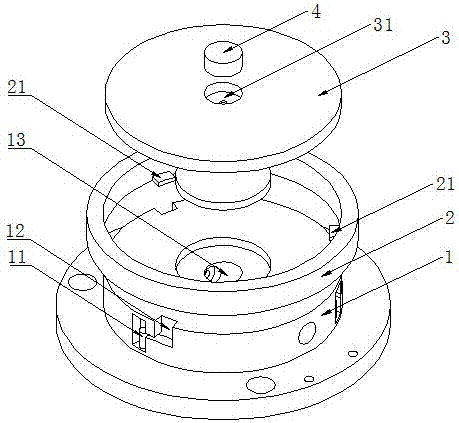
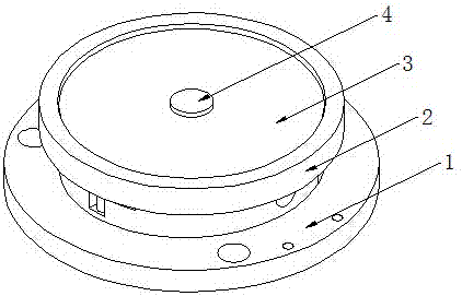
[0046] A kind of novel emery wheel mold of the present embodiment, as figure 1 , figure 2 , image 3 As shown, it is mainly realized through the following technical solutions: a new type of grinding wheel mould, including a bottom mold 1, an upper mold 2, an inner mold 3 and a core mold 4, and the core mold 4 is plugged into a core provided at the center of the top surface of the inner mold 3 In the hole 31; the bottom mold 1 includes a limit card groove 11, a limit elastic member 12 and a demoulding channel 13 arranged inside the bottom mold 1, and the side wall of the demoulding channel 13 is provided with auxiliary positioning holes; the limit card The slot 11 is in the shape of an inverted "h" and is arranged on the outer cylindrical surface of the bottom mold 1. The limit card slot 11 includes an installation slot 111 and a working slot 112 which communicate with each other. The limiting elastic member 12 is arranged in the working slot 112. One end of 111 is connected...

Embodiment 2

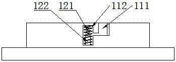
[0052] This embodiment is further optimized on the basis of the above embodiments, such as Figure 5 As shown, further, the first contact surface of the limit card is in contact with the second contact surface of the limit card groove, and a gap is provided between the inner ring surface of the upper mold and the outer cylindrical surface of the bottom mold. Other parts of this embodiment are the same as those of the foregoing embodiments, so details are not repeated here.

Embodiment 3

[0054] This embodiment is further optimized on the basis of the above embodiments, such as Figure 4 , Figure 5 As shown, further, the bottom mold 1 includes a plurality of limit elastic members 12, and the plurality of limit elastic members 12 are evenly distributed on the outer cylindrical surface of the bottom mold 1; the limit elastic members 12 include limit columns and elastic The connecting piece 122, the limiting column is a rigid cylinder, the elastic connecting piece 122 is sleeved on the limiting column and the upper end surface of the elastic connecting piece 122 is higher than the upper end surface of the limiting column; the upper end surface of the elastic connecting piece 122 is in contact with the limiting column The bottom surface of the bit card 21 is in contact with the bottom surface of the elastic connecting member 122 and the bottom surface of the working slot 112 . Other parts of this embodiment are the same as those of the foregoing embodiments, so d...


PUM


Abstract

The invention discloses a new type of grinding wheel mould, comprising a bottom mold, an upper mold, an inner mold and a core mold, the core mold is plugged into a core hole on the top surface of the inner mold; the bottom mold includes a limit card slot, a limit elastic parts and the demoulding channel arranged inside the bottom mold; the limit card slot is in the shape of an inverted "h" and is arranged on the outer cylindrical surface of the bottom mold. The elastic part is arranged in the working groove, and the installation groove is connected with the working groove and the top surface of the bottom mold; the upper mold is respectively overlaid on the inner mold and the bottom mold, and the bottom surface of the inner mold is in contact with the top surface of the bottom mold; Position card, the bottom surface of the limit card conflicts with the top surface of the limit elastic part and is engaged with the limit card slot; the inner wall of the upper mold that is higher than the top surface of the inner mold and the top surface of the inner mold are provided with a grinding wheel formed cavity. The invention can reduce the friction loss of the mould, guarantee the production quality of the grinding wheel and prolong the service life of the mould.

Description

technical field [0001] The invention relates to the field of grinding wheel manufacturing, in particular to a novel grinding wheel mold. Background technique [0002] As we all know, a grinding wheel is a tool for cutting or grinding, and a grinding wheel mold is a device for manufacturing grinding wheels. The existing grinding wheel mold mainly includes an outer mold, an inner mold and a mold core. A cavity is formed between the inner wall of the outer mold and the plane of the inner mold, and sand grains are set. The mold is pressed by a high-pressure head to form a grinding wheel, and finally the grinding wheel is obtained through demoulding. piece. During the pressing process, the mold bears a large pressure, and at the same time, the relative movement between the outer mold and the inner mold is relatively long, resulting in greater friction. The friction consumption caused by friction will affect the quality of the grinding wheel on the one hand, and reduce the mold o...

Claims


Application Information

Patent Timeline
Patent Type & Authority Applications(China)
IPC IPC(8): B24D18/00
CPCB24D18/0009
Inventor 张欢
Owner 成都圻坊生物科技有限公司
Why Eureka
Try Eureka