A kind of cooling structure and method of beryllium copper slider

A technology of cooling structure and cooling method, which is applied to the cooling structure of die sliders and the cooling structure of beryllium copper sliders, can solve the problems of long cooling time, poor cooling effect, and the cooling effect cannot meet the requirements, so as to ensure the cooling quality. , the effect of improving the cooling effect

Active Publication Date: 2019-05-31
YANCHENG JIANDE MOLD PLASTIC
View PDF7 Cites 0 Cited by
  • Summary
  • Abstract
  • Description
  • Claims
  • Application Information

AI Technical Summary

Problems solved by technology

[0002] Since the melting temperature of the injection molding raw materials used is about 320°C when the mold is used to manufacture injection molded products, and the mold release temperature of the injection molded product is about 70°C for solidification and molding, the cooling time required is longer, and due to the wall thickness of the injection molded product itself If it is too thick, during the solidification and molding process of the injection molded product, the demand for cooling heat exchange is greater, and a medium with a lower temperature and a larger flow rate is required. Even if the beryllium copper slider insert with higher thermal conductivity is used, the cooling effect It still does not meet the requirements, especially the cooling effect of the head molding part of the beryllium copper slider insert is even worse

Method used


Image

  • A kind of cooling structure and method of beryllium copper slider
  • A kind of cooling structure and method of beryllium copper slider

Examples


Embodiment Construction

[0020] The present invention will be described in detail below in conjunction with the accompanying drawings and embodiments.

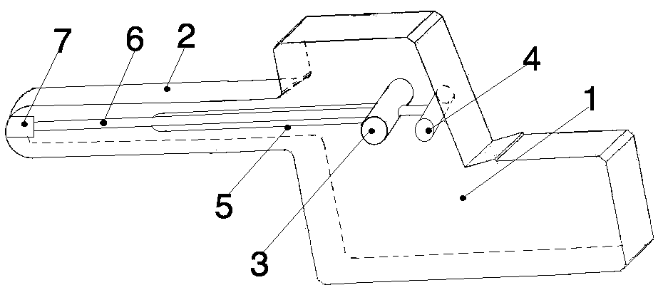
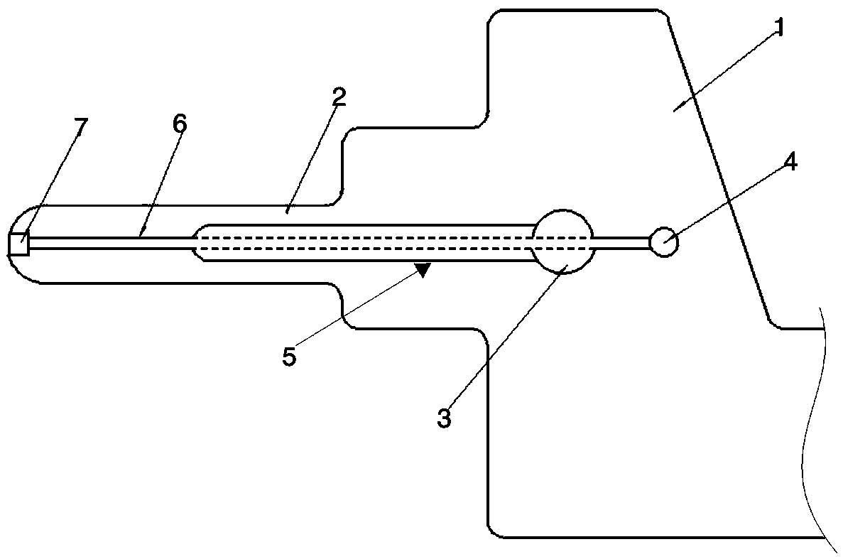
[0021] like figure 1 and 2 As shown: this embodiment is a cooling structure of a beryllium copper slider, including a slider body 1 and a beryllium copper insert 2 arranged on the slider body 1, and the inside of the slider body 1 is provided with a cooling main water pipe 3 and The cooling main air pipe 4, the cooling main water pipe 3 communicates with the external water supply device, the cooling main air pipe 4 communicates with the external air supply device, the inside of the slider body 1 and the beryllium copper insert 2 is provided with a cooling auxiliary water pipe 5 and a cooling auxiliary air pipe 6, The right end of the auxiliary cooling water pipe 5 is located in the slider body 1 and communicates with the main cooling water pipe 3. The left end of the auxiliary cooling water pipe 5 is located inside the beryllium copper insert 2 and h...


PUM


Abstract

Disclosed is a cooling structure of a beryllium copper sliding block. The cooling structure of the beryllium copper sliding block comprises a sliding block body and a beryllium copper insert, wherein the beryllium copper insert is arranged on the sliding block body. A cooling main water pipe and a cooling main gas pipe are arranged inside the sliding block body, and a cooling auxiliary water pipe and a cooling auxiliary gas pipe are arranged inside the sliding block body and the beryllium copper insert. One end of the cooling auxiliary water pipe is located in the sliding block body and communicated with the cooling main water pipe. The other end of the cooling auxiliary water pipe is located inside the beryllium copper insert and not provided with an outlet. The cooling auxiliary gas pipe penetrates through the cooling main water pipe and the cooling auxiliary water pipe. The end, penetrating out of the cooling main water pipe, of the cooling auxiliary gas pipe is located in the sliding block body and communicated with the cooling main gas pipe, and the end, penetrating out of the cooling auxiliary water pipe, of the cooling auxiliary gas pipe is located in the beryllium copper insert and communicated with a gas valve arranged on the beryllium copper insert. The cooling structure of the beryllium copper sliding block meets the requirement of injection molding products for cooling heat exchange in the curing molding process, improves the cooling effect of a beryllium copper sliding block insert and guarantees the cooling quality of a head molding part of the beryllium copper sliding block insert.

Description

technical field [0001] The invention relates to a cooling structure and method of a mold slider, in particular to a cooling structure and method of a beryllium copper slider, which belongs to the technical field of molds. Background technique [0002] Since the melting temperature of the injection molding raw materials used is about 320°C when the mold is used to manufacture injection molded products, and the mold release temperature of the injection molded product is about 70°C for solidification and molding, the cooling time required is longer, and due to the wall thickness of the injection molded product itself If it is too thick, during the solidification and molding process of the injection molded product, the demand for cooling heat exchange is greater, and a medium with a lower temperature and a larger flow rate is required. Even if the beryllium copper slider insert with higher thermal conductivity is used, the cooling effect It still cannot meet the requirements, es...

Claims


Application Information

Patent Timeline
Patent Type & Authority Patents(China)
IPC IPC(8): B29C45/73
CPCB29C45/73
Inventor 尹忠慰耿卫兵曹文成
Owner YANCHENG JIANDE MOLD PLASTIC
Why Eureka
Try Eureka