Simple hot pressing method

A simple and iron technology, applied in the field of automatic machinery and equipment, can solve problems such as affecting the relative position of plastic parts and metal parts, complex process equipment, damage to plastic parts, etc., to achieve the effect of simple structure, convenient operation and convenient maintenance

Inactive Publication Date: 2017-12-08
WUXI HOUFA AUTOMATIC EQUIP CO LTD
View PDF5 Cites 3 Cited by
  • Summary
  • Abstract
  • Description
  • Claims
  • Application Information

AI Technical Summary

Problems solved by technology

[0005] However, its process equipment is relatively complicated, requiring multiple compression cylinders, and when fixing the plastic part, the plastic part is divided into several parts, and several parts are positioned separately. Once a compression cylinder is in the wrong position during use, it will Damage to plastic parts will affect the relative position of plastic parts and metal parts

Method used


Image

  • Simple hot pressing method
  • Simple hot pressing method
  • Simple hot pressing method

Examples


Embodiment 1

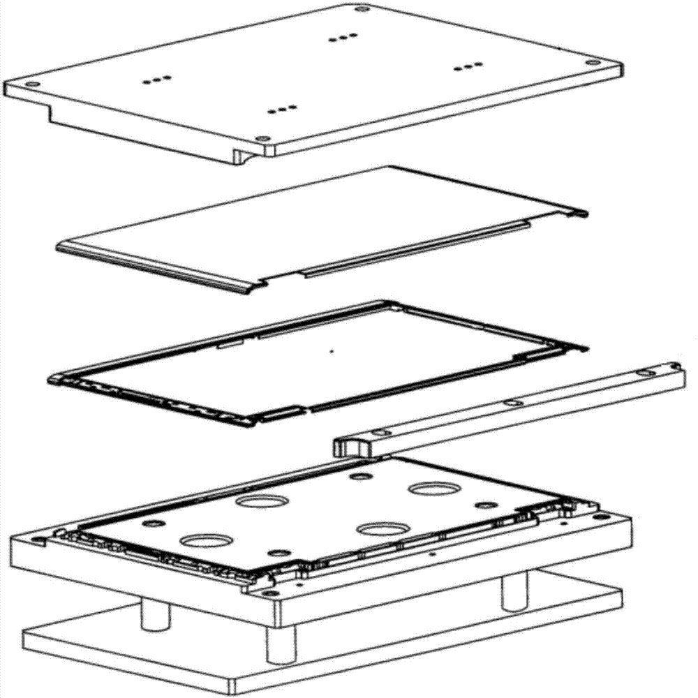
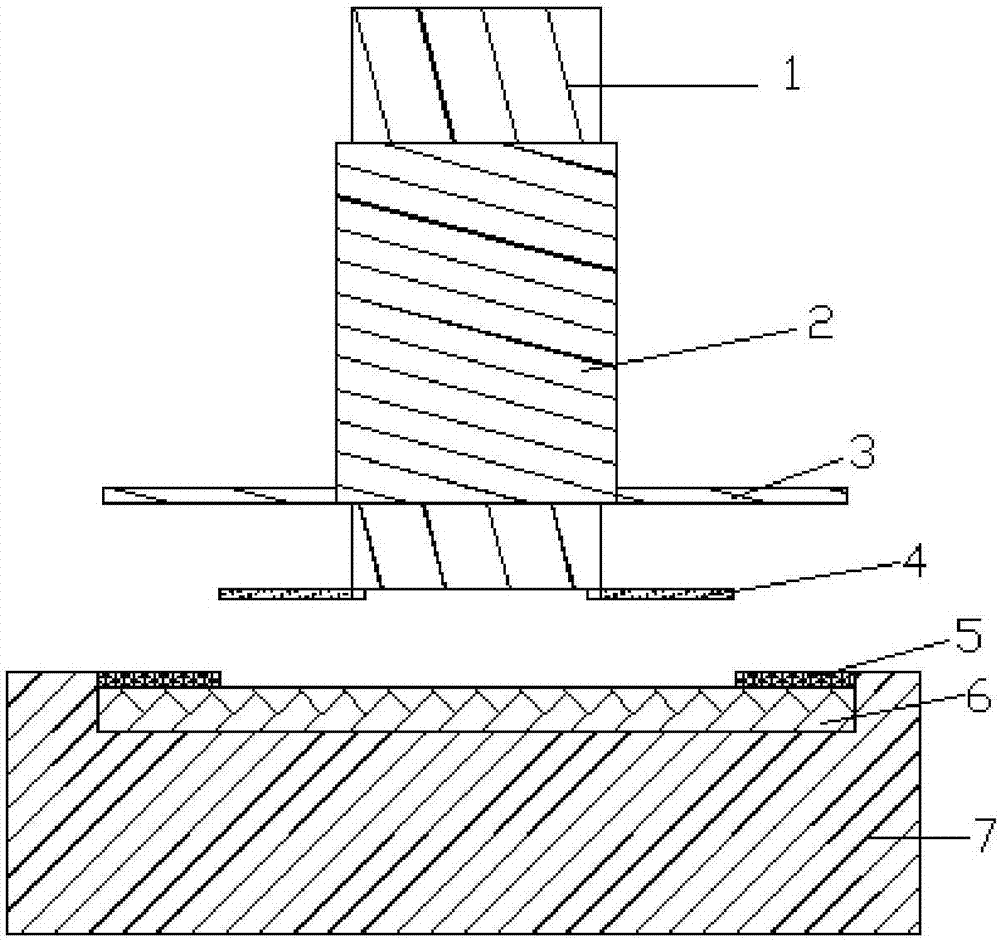
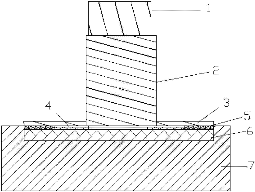
[0032] as attached figure 2 , 3 A simple thermocompression bonding device shown includes a fixed seat, a rotating rod arranged above the fixed seat, and a pressing part, wherein the centerlines of the rotating rod, the pressing part and the fixing seat are on the same straight line ;

[0033] There is a groove on the fixing seat, the depth of the groove is not less than the sum of the height of the iron part and the plastic part, and the groove can realize the limit of the iron part; in specific use, the groove can realize the complete limit of the iron part , can also realize partial limit of plastic parts;

[0034] Such as Figure 4 , 5 The rotating rod shown can rotate around its own axis under the action of external force. The rotating rod is provided with a rotating blade near the end of the fixed seat. The rotating blade can rotate with the rotation of the rotating rod and realize the gluing of pushing the plastic part to the iron part. location;

[0035] The pres...

Embodiment 2

[0049] The difference from Example 1 is that in order to adapt to plastic parts of different specifications, the rotating blade is installed on one end of the rotating rod through the rotating shaft; the rotating blade can rotate within the range of -30°-30° around the rotating shaft (further, The rotating blade is mounted on one end of the rotating rod through the rotating shaft and the torsion spring. The function of the torsion spring is that when the rotating blade rotates around the rotating shaft beyond the range of -30°-30°, it can bring the rotating blade back and make the rotating blade return to its original position). The preferred rotating blades are fan-shaped. When the rotating blades have different angles around the rotating shaft, the linear distance between the rotating blades and the plastic parts will also be different, so that the thermocompression bonding of plastic parts and iron parts of different sizes can be realized.

[0050]Further, there are two rota...


PUM


Abstract

The invention belongs to the field of automatic mechanical equipment, and in particular, relates to a simple hot pressing method. The simple hot pressing method comprises the following steps: (1) an iron piece is put in a groove of a fixed base; (2) the iron piece is glued; and a plastic part is put on the iron piece; (3) relative positions of a rotating shaft and the fixed base are adjusted; (4) a rotating rod is driven to rotate under the effect of external force; (5) the rotating rod is continuously rotated; and meanwhile, the position of a sleeve on the rotating rod is adjusted; (6) the rotating rod is continuously rotated until the plastic part and the iron piece are totally glued in a gluing position on the iron piece; (5) the rotating rod is continuously rotated; and the position of the sleeve can guarantee the acting force of a pressure applying piece on the upper surface of the plastic part; and (6) the rotating rod is continuously rotated until the plastic part and the iron piece are totally glued. The simple hot pressing method can effectively realize accurate positioning and gluing of the plastic part and the iron piece.

Description

technical field [0001] The invention belongs to the field of automatic mechanical equipment, and relates to a thermocompression mechanism, in particular to a simple thermocompression method. Background technique [0002] Such as figure 1 As shown, in the prior art, when a plastic part will be glued and fixed on an iron part, it must first be placed on the male mold surface of the iron part (ie figure 1 Dispens glue on the corresponding position on the side of the middle iron part facing downward), and then place the plastic part and the iron part on a positioning jig after dispensing glue, wherein the plastic part is located below the iron part, and pass A positioning bar fixes the plastic part and the iron part on the positioning jig, and the positioning jig is supported by a base. Afterwards, a pressing plate is preheated to 100-120 degrees and acts on the iron part, so that heat-conducting melt glue is produced between the iron part and the plastic part. After a period...

Claims


Application Information

Patent Timeline
Patent Type & Authority Applications(China)
IPC IPC(8): B29C65/40
CPCB29C65/40B29C66/74283B29C66/80
Inventor 钱国东
Owner WUXI HOUFA AUTOMATIC EQUIP CO LTD
Why Eureka
Try Eureka