Tail spring device of drum vacuum valve

A technology of vacuum valve and spring device, which is applied in the field of uranium enrichment, can solve the problems of easily damaged welds and hidden dangers of valve reliability, and achieve the effect of improving service life

Active Publication Date: 2017-12-08
CNNC SEVENTH RES & DESIGN INST CO LTD
View PDF3 Cites 2 Cited by
  • Summary
  • Abstract
  • Description
  • Claims
  • Application Information

AI Technical Summary

Problems solved by technology

But when the spring is compressed, the force is mainly on the bottom plate of the cover tube, more precisely, the weld seam at the bottom plate. This structure brings certain hidden dangers to the reliability of the valve. With the increase of the valve opening times, the weld Seams are easily damaged

Method used


Image

  • Tail spring device of drum vacuum valve

Examples


Embodiment Construction

[0018] The technical solution of the present invention will be described in detail below in conjunction with the accompanying drawings and specific embodiments.

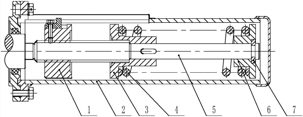
[0019] Such as figure 1 As shown, the tail spring device of a drum vacuum valve in the present invention connects the sleeve assembly to the external system through bolts, including a worm shaft, a nut assembly, a spring assembly and a sleeve assembly;

[0020] The nut assembly consists of a nut and a slider. The slider is an L-shaped plate. The trapezoidal thread part at the end of the worm shaft is connected to the slider through screws and nuts in the length direction of the slider. The slider is stuck on the sleeve in its height direction. In the U-shaped groove of the component to limit the rotational movement of the nut component;

[0021] When the worm shaft rotates, the nut assembly does not rotate with the worm, but slides along the axial direction of the worm shaft, and at the same time slides linearly alo...


PUM


Abstract

The invention belongs to a uranium hexafluoride system in the field of uranium enrichment, and particularly relates to a tail spring device applied to a drum vacuum valve in the system. The tail spring device comprises a worm shaft, a nut assembly, a spring assembly and a sleeve assembly, wherein the sleeve assembly is connected to an external system through bolts; when a valve does switch-on and switch-off actions, a motor drives the worm shaft to rotate, the nut assembly linearly slides to a spring base to compress a spring through the action of a U-shaped groove of the sleeve assembly, the spring transmits force borne by the spring to the base, and the force is exerted on the worm shaft through a half gasket; counterforce generated through spring compression hinders rotation of the worm shaft, the friction force of the worm shaft is increased, and then the moment transmitted by the worm shaft is decreased. According to the tail spring device, the compressing force of the spring is borne by the worm shaft, the sleeve assembly does not bear the elastic force any more, therefore, the service life of a sleeve is prolonged, and the reliability of the valve is improved.

Description

technical field [0001] The invention belongs to a uranium hexafluoride system in the field of uranium enrichment, and in particular relates to a tail spring device applied to a drum vacuum valve in the system. Background technique [0002] Drum vacuum valve is an important equipment in uranium enrichment system. The characteristic of this kind of valve closing action is that the driving mechanism drives the valve core assembly to rotate 90° and then stops the rotation, and then pushes the closing disc in the valve core assembly to go straight to the valve port to achieve channel sealing. When the spool assembly rotates 90° driven by the main shaft, the spool assembly hits the thrust head and stops rotating; when the main shaft continues to rotate, the closing disk in the spool assembly goes straight under the track of the cam, and finally presses the sealing surface. In the process of hitting the thrust head and pressing the sealing surface, there will be an impact. The fun...

Claims


Application Information

Patent Timeline
Patent Type & Authority Applications(China)
IPC IPC(8): F16F7/00F16K31/53
CPCF16F7/00F16K31/53
Inventor 殷亚芳刘洋吴刚薛光磊范国伟郭琦钟雄
Owner CNNC SEVENTH RES & DESIGN INST CO LTD
Why Eureka
Try Eureka