Eureka AIR delivers breakthrough ideas for toughest innovation challenges, trusted by R&D personnel around the world.

Double-rod control mechanism

A lever-operated, one-pair technology, applied in mechanical equipment, components with teeth, belts/chains/gears, etc., to solve problems such as obstacles to the driver's judgment ability, high friction coefficient, and high noise, and achieve a good driving environment. , the effect of low vibration and low noise

Active Publication Date: 2017-12-08
ZHEJIANG SAIGE EDUCATION DEVICE TECH CO LTD
View PDF3 Cites 4 Cited by
  • Summary
  • Abstract
  • Description
  • Claims
  • Application Information

AI Technical Summary

Problems solved by technology

[0002] As the control mechanism of the transmission, the control mechanism of the automobile transmission occupies a pivotal position in the overall structure of the transmission. The transmission control mechanism is a set of mechanisms that the driver manipulates the shift handle to make the gearbox shift. Only when the driver operates comfortably and safely can he To ensure the safety of the driving process, many riders often encounter the problem of hand numbness caused by the vibration of the shift lever during driving, and the shift lever makes a loud noise. As we all know, the vibration will also generate resonance. Machinery is very harmful. Due to vibration, the machine often produces huge and repeatedly changing loads during use, resulting in a reduction in the service life of the machine, and even a catastrophic damage accident. The accompanying noise has a certain impact on the driver's judgment ability. Obstacles, in severe cases, cause traffic accidents
[0003] Chinese patent CN104006151.B discloses a double lever operating mechanism, including a shift mechanism, a gear selection mechanism and a conversion bracket; The body consists of the first cylinder, the second cylinder and the third cylinder with successively smaller diameters on the bottom surface. The single bush itself bears the friction and impact of the shift arm, with little effect, and the bush and the shaft are linear Contact, the friction force is sliding friction, the friction coefficient is large, and the wear on the bushing is very large, which puts forward very high requirements on the material of the bushing itself, corresponding to a high cost

Method used


Image

  • Double-rod control mechanism
  • Double-rod control mechanism
  • Double-rod control mechanism

Examples


Embodiment Construction

[0028] The following will clearly and completely describe the technical solutions in the embodiments of the present invention with reference to the accompanying drawings in the embodiments of the present invention. Obviously, the described embodiments are only some, not all, embodiments of the present invention. Based on the embodiments of the present invention, all other embodiments obtained by persons of ordinary skill in the art without making creative efforts belong to the protection scope of the present invention.

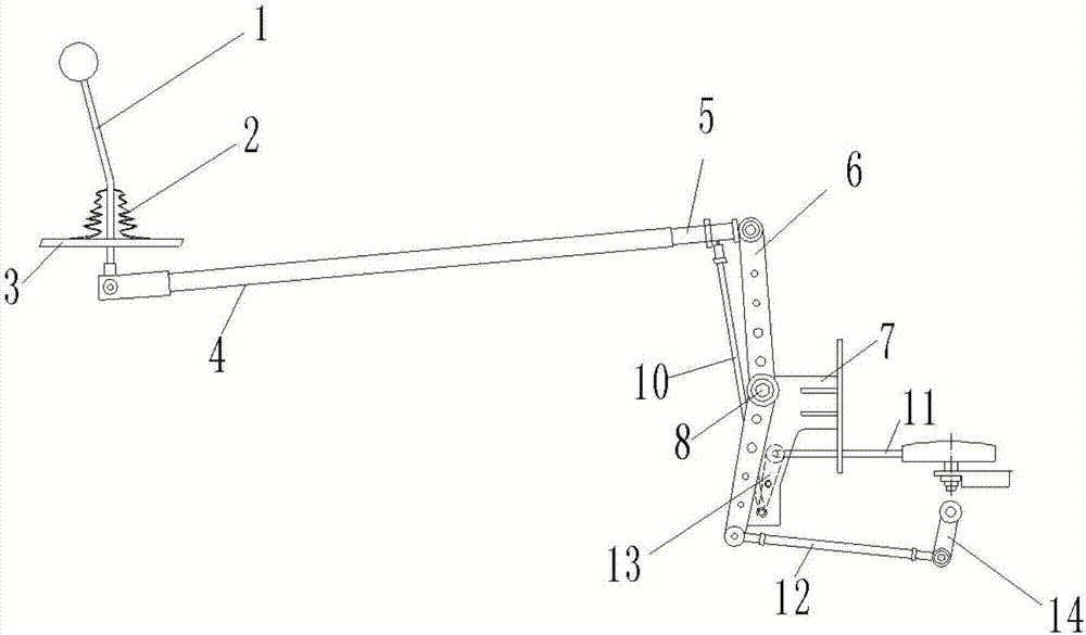
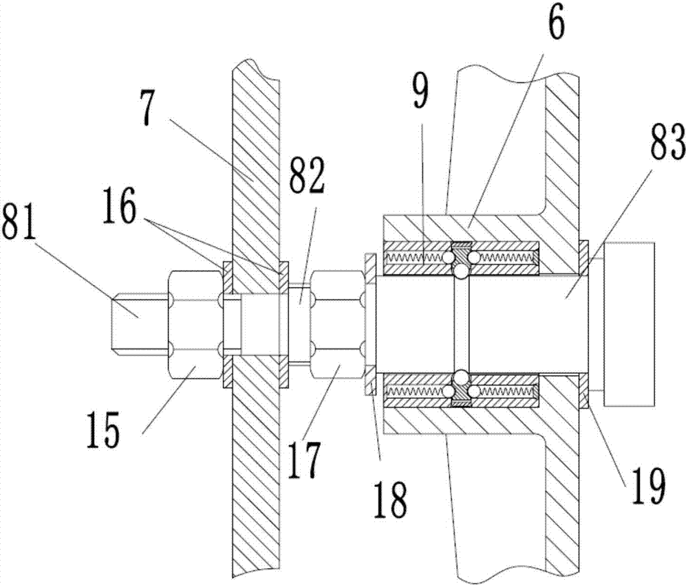
[0029] refer to Figure 1 to Figure 7 ,Such as figure 1 A double-rod operating mechanism shown includes a shift lever 1, a pull rod 5, a shift swing arm 6, a shift rocker arm 14, a shift shaft 8, a first select connecting rod 10, a select swing arm 13, The conversion bracket 7 and the second gear selection connecting rod 11, the shift rod 1 is fixed on the cab floor 3 through the support, the lower part of the shift rod 1 has a dust cover 2, and the shift rod...


PUM


Abstract

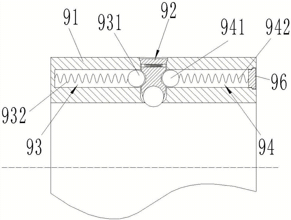
The invention discloses a double-rod control mechanism comprising a gear shift rod, a pull rod, a gear shift swing arm, a gear shift rocker, a gear shift rotary shaft, a first gear selecting connecting rod, a gear selecting swing arm, a switching support and a second gear selecting connecting rod. The middle of the gear shift swing arm can rotate around the gear shift rotary shaft. The double-rod control mechanism further comprises a vibration reduction bearing installed between the gear shift rotary shaft and the gear shift swing arm. The vibration reduction bearing is used for supporting the gear shift swing arm and buffering the impact force between the gear shift rotary shaft and the gear shift swing arm, in this way, vibration from the inside of a gearbox is transmitted to the vibration reduction bearing to be buffered, numbness and discomfort of hands of a driver due to vibration are reduced, the gear-off problem caused by nut loosening caused by vibration is also reduced, and potential safety hazards are reduced greatly.

Description

technical field [0001] The invention relates to the field of shift control systems for heavy trucks, in particular to a double-bar control mechanism. Background technique [0002] As the control mechanism of the transmission, the control mechanism of the automobile transmission occupies a pivotal position in the overall structure of the transmission. The transmission control mechanism is a set of mechanisms that the driver manipulates the shift handle to make the gearbox shift. Only when the driver operates comfortably and safely can he To ensure the safety of the driving process, many riders often encounter the problem of hand numbness caused by the vibration of the shift lever during driving, and the shift lever makes a loud noise. As we all know, the vibration will also generate resonance. Machinery is very harmful. Due to vibration, the machine often produces huge and repeatedly changing loads during use, resulting in a reduction in the service life of the machine, and e...

Claims


Application Information

Patent Timeline
Patent Type & Authority Applications(China)
IPC IPC(8): F16H59/02
CPCF16H59/0208F16H59/0278
Inventor 翁景坚赵锡峰
Owner ZHEJIANG SAIGE EDUCATION DEVICE TECH CO LTD
Why Eureka
Eureka Blog
Learn More