Labyrinth seal device with adjustable seal clearance

A labyrinth seal and gap seal technology, which is applied to engine seals, transmission parts, engine components, etc., can solve problems such as energy waste, collisions, and large energy waste

Pending Publication Date: 2017-12-08
孟金来
View PDF0 Cites 2 Cited by
  • Summary
  • Abstract
  • Description
  • Claims
  • Application Information

AI Technical Summary

Problems solved by technology

The leakage of the labyrinth seal is proportional to the size of the throttling backlash. Considering the sealing performance, it is hoped that the throttling backlash should be as small as possible, because the increased leakage of the labyrinth seal will lead to a lot of energy waste
But if the throttling backlash is designed to be very small, for steam turbines, gas turbines and other equipment with long shafts, in the process of starting and stopping, the speed of the shaft needs to pass through more than one critical speed during the change process. Near the critical speed, the vibration of the rotating shaft will increase sharply, which will cause friction or even collision between the comb teeth and the rotating shaft, resulting in a larger throttling backlash, and may even cause the labyrinth seal to lose its sealing effect due to the breakage of the comb teeth
Therefore, for those equipment whose rotating shaft beats greatly during the process of starting and stopping the rotation, people have to design the throttling backlash of the labyrinth seal to be relatively large, which leads to a large waste of energy during the operation of the equipment.

Method used


Image

  • Labyrinth seal device with adjustable seal clearance
  • Labyrinth seal device with adjustable seal clearance
  • Labyrinth seal device with adjustable seal clearance

Examples


Embodiment Construction

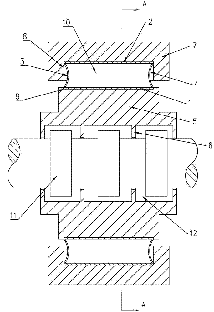
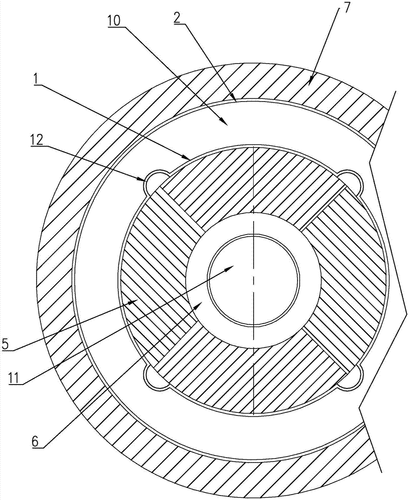
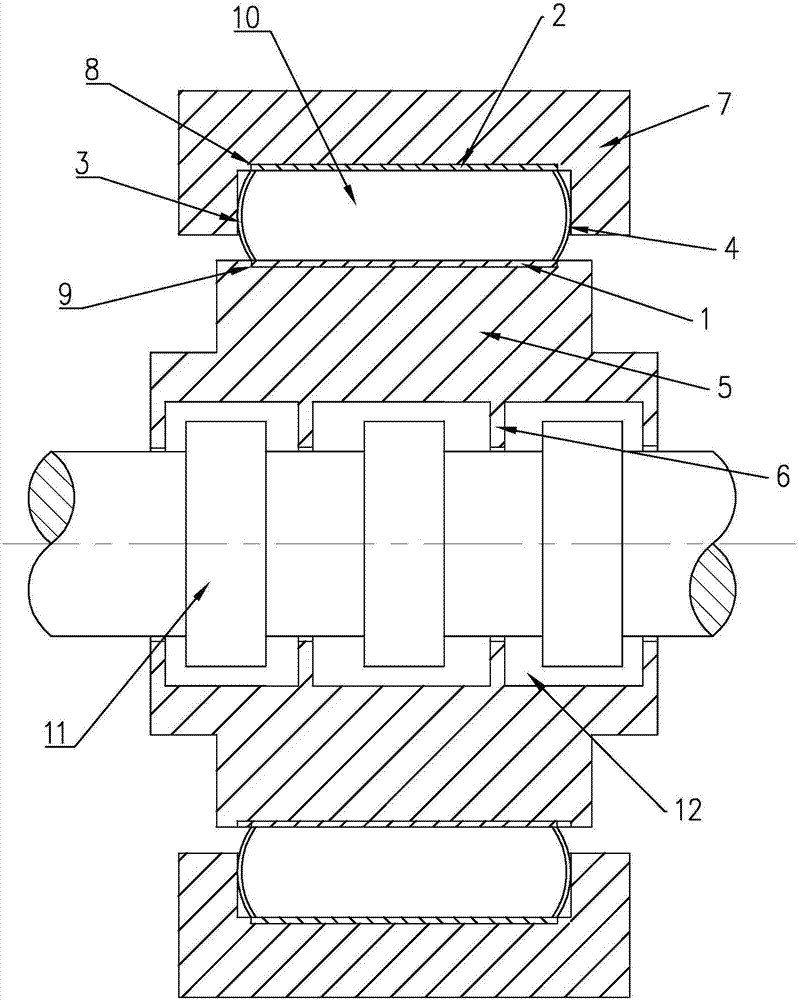
[0019] Such as figure 1 , figure 2 with image 3 As shown, the labyrinth sealing device with adjustable sealing gap of the present invention includes an annular comb-tooth seat push-pull ring 1. The comb-tooth seat push-pull ring 1 is preferably a circular ring shape, or an elliptical or other ring shape. An annular outer ring 2 is arranged on the outer side of 1, and the outer ring 2 is arranged in parallel with the comb seat push-pull ring 1, that is, arranged on a concentric shaft.

[0020] The left side of the comb seat push-pull ring 1 is connected to the inner end of the annular left pull plate 3, usually by welding. The comb seat push-pull ring 1 and the left pull plate 3 can also form the comb seat push-pull ring 1 and The metal plates of the left pull plate 3 are made of the same material and connected as a whole structure;

[0021] The right side of the comb seat push-pull ring 1 is connected to the inner end of the annular right pull plate 4, usually by welding. The co...


PUM


Abstract

A labyrinth sealing device with an adjustable sealing gap, comprising an annular comb seat push-pull ring, an annular outer ring is arranged on the outside of the comb tooth seat push-pull ring, the left end side of the comb tooth seat push-pull ring and the annular left pull plate The inner end is connected, the right end side of the comb seat push-pull ring is connected with the inner end of the annular right pull plate, the left end side of the outer ring is connected with the outer end of the annular left pull plate, the right end side of the outer ring is connected with the annular The outer end of the right pull plate is connected, and the push-pull ring of the comb seat, the left pull plate, the right pull plate and the outer ring form a ring-shaped pressure working chamber, and the ring of the push-pull ring of the comb seat is surrounded by a plurality of comb seats , the outer end of the comb seat is fixedly connected with the push-pull ring of the comb seat, and the comb seat can move radially under the action of the push-pull ring of the comb seat. The purpose is to provide a labyrinth sealing device with adjustable sealing gap which can effectively reduce the leakage of the sealing system, reduce the energy waste during the operation of the equipment, and improve the service life of the labyrinth seal.

Description

Technical field [0001] The invention relates to a labyrinth sealing device with adjustable sealing gap. Background technique [0002] Labyrinth seal is also called comb seal, which is a non-contact seal. It is mainly used to seal gaseous media. It has a wide range of applications as interstage seals, shaft end seals and tip seals, or other dynamic seals in front of steam turbines, gas turbines, centrifugal compressors, blowers and other machines. The leakage of the labyrinth seal is proportional to the size of the throttle backlash. Considering the sealing performance, it is hoped that the throttle backlash should be as small as possible, because the increase of the leaking volume of the labyrinth seal will cause a lot of energy waste. However, if the throttle backlash is designed to be very small, for steam turbines, gas turbines and other equipment with long shafts, during the process of starting and stopping the rotation, the speed of the shaft needs to pass more than one cri...

Claims


Application Information

Patent Timeline
Patent Type & Authority Applications(China)
IPC IPC(8): F16J15/447F16H57/029
CPCF16J15/4476F16H57/029
Inventor 孟金来
Owner 孟金来
Why Eureka
Try Eureka