Liftable transformer placing rack

A technology for placing racks and transformers, applied in the field of placing racks, can solve the problems of unsafe maintenance, unstable placement, inconvenient adjustment, etc.

Inactive Publication Date: 2017-12-08
绍兴科普织造有限公司
View PDF1 Cites 12 Cited by
  • Summary
  • Abstract
  • Description
  • Claims
  • Application Information

AI Technical Summary

Problems solved by technology

[0005] In order to overcome the disadvantages of inconvenient adjustment, unstable placement and unsafe maintenance of the existing transformer placement rack, the technical problem to be solved by the present invention is to provide a liftable transformer placement rack with convenient adjustment, stable placement and safe maintenance

Method used


Image

  • Liftable transformer placing rack
  • Liftable transformer placing rack
  • Liftable transformer placing rack

Examples


Embodiment 1

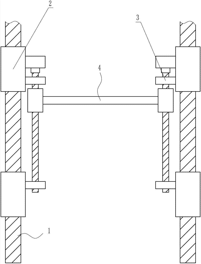
[0039] A lifting transformer placement frame, such as Figure 1-9 As shown, it includes a fixing device 2, a lifting device 3 and a placement plate 4, a lifting device 3 is arranged between the left and right sides of the fixing device 2, and a placement plate 4 is connected in the middle of the lifting device 3.

Embodiment 2

[0041] A lifting transformer placement frame, such as Figure 1-9 As shown, it includes a fixing device 2, a lifting device 3 and a placement plate 4, a lifting device 3 is arranged between the left and right sides of the fixing device 2, and a placement plate 4 is connected in the middle of the lifting device 3.

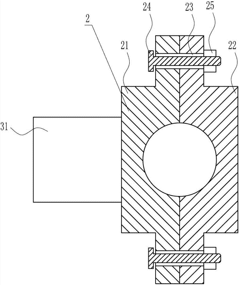
[0042] The fixing device 2 includes a first block 21, a second block 22, a bolt 24 and a nut 25, the first block 21 and the second block 22 are arranged symmetrically on the left and right, and the first block 21 and the second block 22 The front part and the rear part of all have through holes 23, and the through holes 23 in the front part and the rear part of the first block 21 and the second block 22 are connected, and the through holes 23 are provided with bolts 24, and the right ends of the bolts 24 are provided with There is a nut 25 through which the bolt 24 passes.

Embodiment 3

[0044] A lifting transformer placement frame, such as Figure 1-9 As shown, it includes a fixing device 2, a lifting device 3 and a placement plate 4, a lifting device 3 is arranged between the left and right sides of the fixing device 2, and a placement plate 4 is connected in the middle of the lifting device 3.

[0045] The fixing device 2 includes a first block 21, a second block 22, a bolt 24 and a nut 25, the first block 21 and the second block 22 are arranged symmetrically on the left and right, and the first block 21 and the second block 22 The front part and the rear part of all have through holes 23, and the through holes 23 in the front part and the rear part of the first block 21 and the second block 22 are connected, and the through holes 23 are provided with bolts 24, and the right ends of the bolts 24 are provided with There is a nut 25 through which the bolt 24 passes.

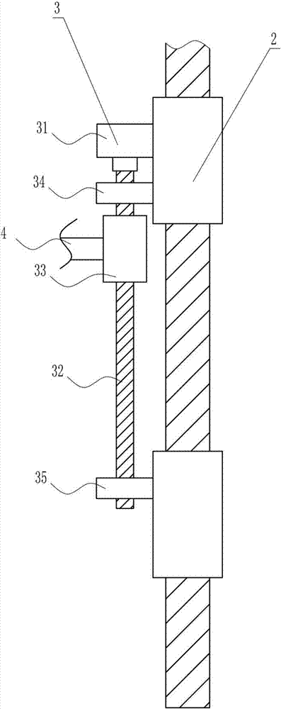
[0046] The lifting device 3 includes a motor 31, a first screw rod 32, a first nut 33, an u...


PUM


Abstract

The invention relates to a placing rack, in particular to a liftable transformer placing rack which comprises fixing devices and the like. Lifting devices are arranged between the left side and the right side of the fixing devices, and a placing plate is arranged between the lifting devices in a connected manner. The liftable transformer placing rack has the advantages that the liftable transformer placing rack is convenient to adjust, and transformers can be stably placed on the liftable transformer placing rack and are safe in maintenance; the lifting devices can be fixed by the aid of the fixing devices, then the transformers can be placed at appropriate locations by the lifting devices, and workers can be elevated by an elevating device, so that the transformers can be maintained by the workers; motors can be powered by storage batteries, and accordingly the liftable transformer placing rack can continue working under power failure conditions.

Description

technical field [0001] The invention relates to a placing frame, in particular to a lifting and lowering transformer placing frame. Background technique [0002] A transformer is a device that uses the principle of electromagnetic induction to change the AC voltage. The main components are a primary coil, a secondary coil and an iron core (magnetic core). In electrical equipment and wireless circuits, it is often used for raising and lowering voltage, matching impedance, safety isolation, etc. The main functions are: voltage conversion, current conversion, impedance conversion, isolation, voltage stabilization (magnetic saturation transformer), etc. According to the purpose, it can be divided into: distribution transformers, power transformers, fully sealed transformers, combined transformers, dry-type transformers, oil-immersed transformers, single-phase transformers, electric furnace transformers, rectifier transformers, etc. [0003] Transformers can be seen everywhere ...

Claims


Application Information

Patent Timeline
Patent Type & Authority Applications(China)
IPC IPC(8): H01F27/06B66F7/14H02B5/02
CPCB66F7/14H01F27/06H02B5/02
Inventor 刘松韩诺赵朋飞
Owner 绍兴科普织造有限公司
Why Eureka
Try Eureka