
A track grounding device

A grounding device and track technology, applied in the direction of connecting contact materials, locomotives, etc., can solve the problems of excessive grounding resistance and small grounding current return, and achieve the effects of prolonging service life, reducing high-frequency impedance, and reducing electromagnetic interference

Active Publication Date: 2019-06-18
CSR ZHUZHOU ELECTRIC LOCOMOTIVE RES INST
View PDF5 Cites 0 Cited by
  • Summary
  • Abstract
  • Description
  • Claims
  • Application Information

AI Technical Summary

Problems solved by technology

[0006] In view of this, the purpose of the present invention is to provide a track grounding device to solve the technical problem of the traditional grounding device due to long-term wear and tear when the carbon brush surface of the grounding device contacts the friction disc, resulting in excessive grounding resistance and small grounding current backflow

Method used


Image

  • A track grounding device
  • A track grounding device
  • A track grounding device

Examples


Embodiment 1

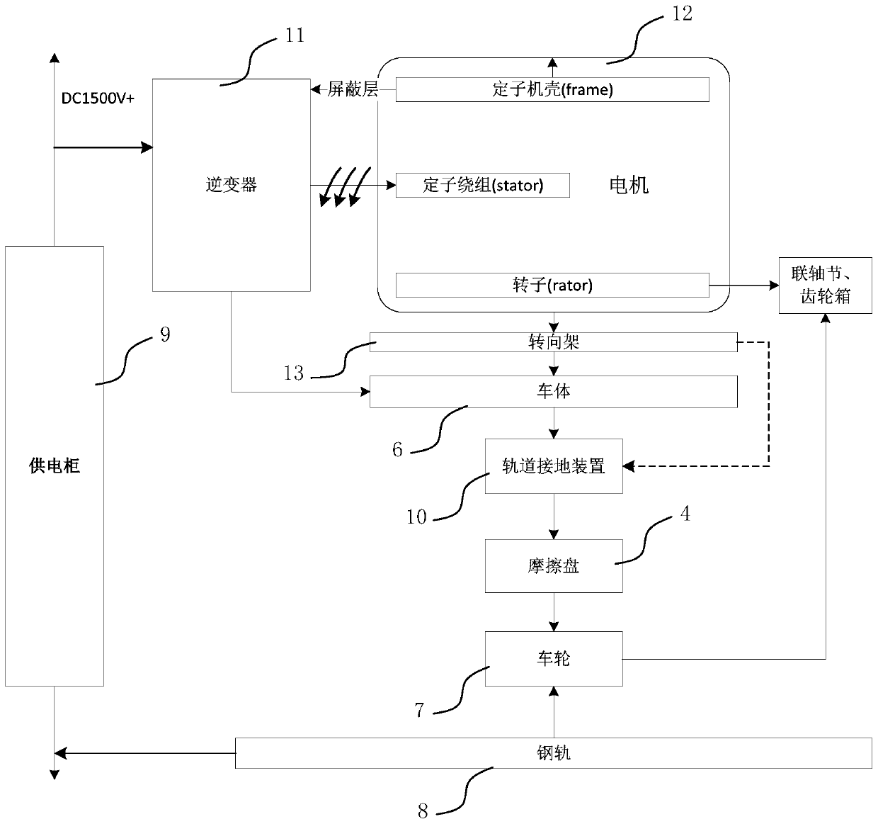
[0051] as attached Figure 4 As shown, a specific embodiment of the track grounding device, the track grounding device 10 is connected between the car body 6 and the friction disc 4, and is used to conduct the electrical connection between the car body 6 and the rail 8 to realize the grounding function. Grounding device 10 includes:

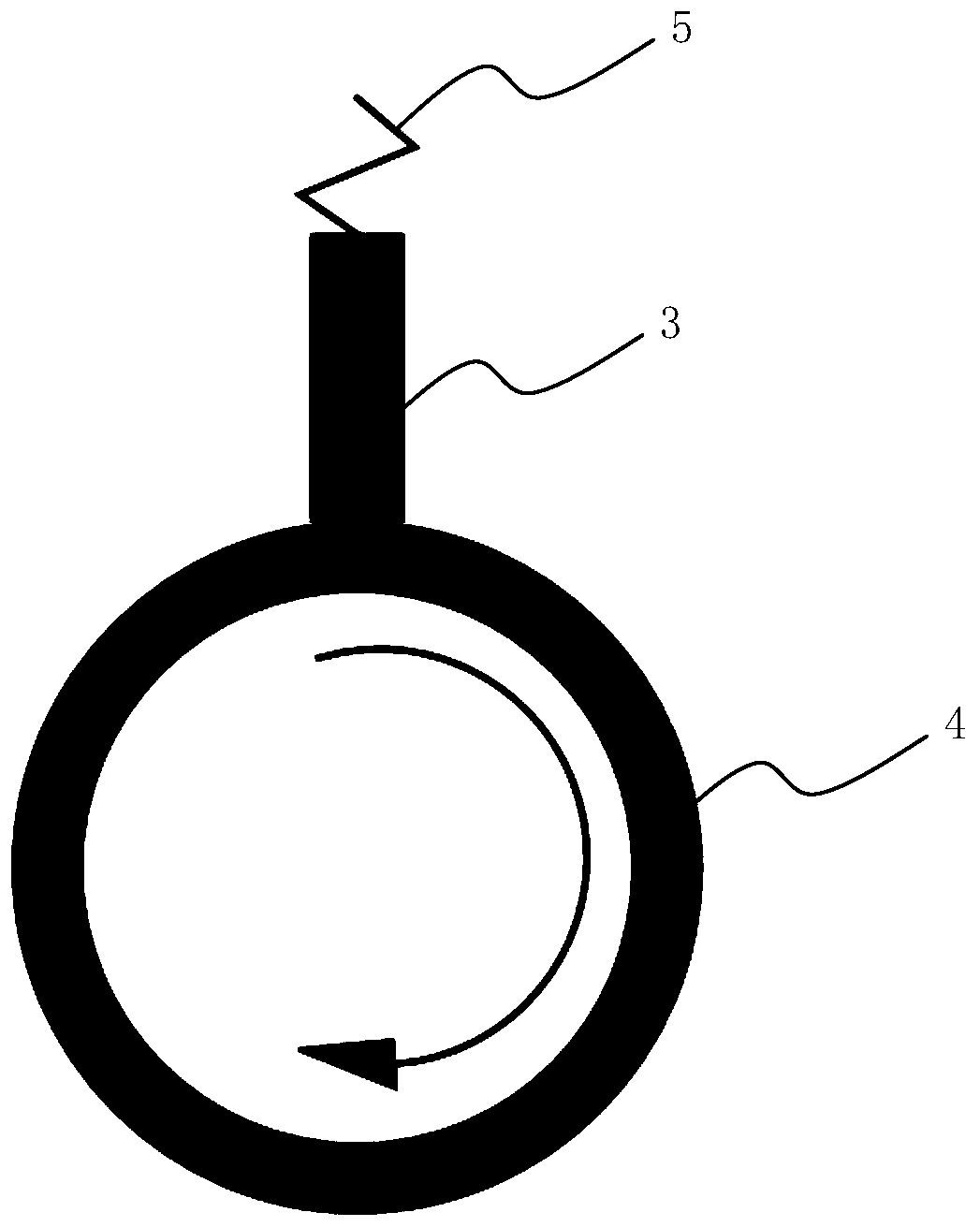
[0052] The rigid brush 3 connected to the car body 6 through the elastic mechanism 5, the rigid brush 3 is in rigid contact with the friction disc 4;

[0053] The flexible brush 1 connected to the rigid brush 3, the flexible brush 1 further includes a base 2 fixedly connected to the rigid brush 3, and a brush wire 20 connected to the base 2, the brush wire 20 is in elastic contact with the friction disc 4 , as attached Figure 6 shown. The base 2 can be reliably connected (including mechanical connection and electrical connection) with the rigid brush 3 by means such as buckle connection, welding, bonding, etc., and at the same time, the flexi...

Embodiment 2

[0066] as attached Figure 5 As shown, a specific embodiment of the track grounding device, the track grounding device 10 is connected between the car body 6 and the friction disc 4, and is used to conduct the electrical connection between the car body 6 and the rail 8 to realize the grounding function. The grounding device 10 includes a flexible brush 1, and the flexible brush 1 further includes:

[0067] connected to the base 2 of the vehicle body 6;

[0068] And the electric brush wire 20 connected to the base 2, the electric brush wire 20 is in elastic contact with the friction disc 4.

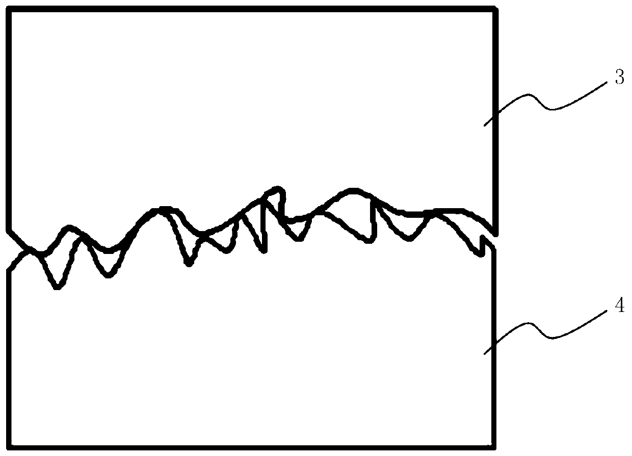
[0069] The flexible brush 1 is in contact with the friction surface of the friction disc 4, and the brush wire 20 of the flexible brush 1 goes deep into the gap of the friction surface, forming several small capacitors between the brush wire 20 of the flexible brush 1 and the friction disc 4, By forming a high-frequency current channel in the contact area between the flexible brush 1 and...

Embodiment 3

[0075] On the basis of Embodiment 1, the rigid brush 3 further surrounds the outer side of the flexible brush 1 in a ring-shaped surrounding structure. For the more detailed technical solutions of the remaining parts, please refer to the corresponding description in Embodiment 1.


PUM


Abstract

The invention discloses a rail grounding device. The rail grounding device is connected between a vehicle body and a friction disc and is used for achieving electrical connection between the vehicle body and a steel rail so as to achieve a grounding function. The device comprises a rigid electric brush and a flexible electric brush, wherein the rigid electric brush is connected to the vehicle body via an elastic mechanism and is in rigid contact with the friction disc, the flexible electric brush is connected with the rigid electric brush and further comprises a base and electric brush wires, the base is fixedly connected to the rigid electric brush, and the electric brush wires are connected to the base and are in elastic contact with the friction disc. By the flexible electric brush, the grounding performance between a direct current and a power frequency alternating current can be effectively improved, and the service lifetime of the rail grounding device is prolonged; and meanwhile, a high-frequency current passage is formed in a contact region of the flexible electric brush and the friction disc, a high-frequency harmonic current in an electric system is favorably flown to the steel rail, and the electromagnetic interference of the system can be effectively reduced. By the rail grounding device, the technical problem of small backflow grounding current caused by excessively large grounding resistance due to long-term abrasion when a surface of a carbon brush of the grounding device is in contact with the friction disc in a traditional grounding device can be solved.

Description

technical field [0001] The invention relates to the technical field of rail transit grounding, in particular to a rail grounding device. Background technique [0002] In the operation of railway vehicles, it is indispensable to keep the bearings in good condition. Once there is an abnormality in the contact part between the track and the vehicle, the bearing will be damaged. The study found that the damage of the bearing is mainly caused by the electric corrosion of the inner wall of the bearing caused by the current flowing through the shaft and the bearing. The current is mainly caused by the axial voltage between the stator and the rotor to break down the oil film of the bearing. The current that causes bearing damage is called electrical discharge machining (Electrical Discharge Machining, EDM) bearing current. The voltage of the switching device rises or falls rapidly in a short time during the rapid breaking process, which will increase the insulation pressure of the...

Claims


Application Information

Patent Timeline
Patent Type & Authority Patents(China)
IPC IPC(8): H01R4/64B61C17/00
CPCB61C17/00H01R4/64
Inventor 范祝霞石煜支永健朱柄全闫光临闵建军杨德勇周伟
Owner CSR ZHUZHOU ELECTRIC LOCOMOTIVE RES INST
Learn More