
Spade-type rotary cultivator

A rotary tiller and shovel-type technology, which is applied in the field of tillage machinery and equipment, can solve the problems of complex rotary tiller blade processing technology, potential safety hazards, and high rotational speed of the cutter shaft, and achieve the effects of compact structure, small motion cycle, and large transmission ratio

Active Publication Date: 2017-12-12
兰州兰石集团兰驼农业装备有限公司
View PDF6 Cites 4 Cited by
  • Summary
  • Abstract
  • Description
  • Claims
  • Application Information

AI Technical Summary

Problems solved by technology

[0003] The purpose of the present invention is to provide a shovel-type rotary tiller to solve the safety hazards caused by the complex processing technology of the existing rotary tiller transmission parts and rotary tiller blades and the high rotational speed of the cutter shaft

Method used


Image

  • Spade-type rotary cultivator
  • Spade-type rotary cultivator
  • Spade-type rotary cultivator

Examples

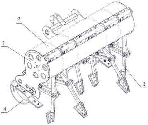
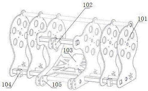
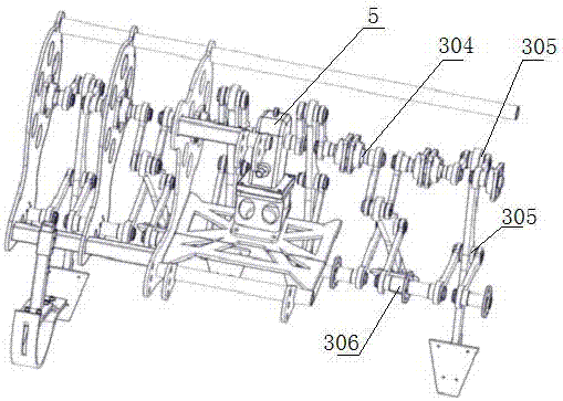

Embodiment Construction

[0026] The present invention will be described in further detail below in conjunction with the accompanying drawings.

[0027] like Figure 1 to Figure 4 A shovel type rotary tiller is shown, which includes a frame welder 1, an array of actuators 3, and a reducer 5. The frame welder 1 includes a reducer connection welder 103, and the two sides of the reducer connection welder 103 There are three connecting plates 101 whose top ends are installed on the crossbeam symmetrically distributed, and the front and bottom ends of the two connecting plates 101 adjacent to the reducer connecting weld 103 are respectively provided with connecting support rods, and upper suspension welded joints are respectively installed on the connecting support rods. 102, lower suspension welding 105; both sides of each connecting plate 101 near the middle are connected with a group of actuators 3, and each group of actuators 3 includes a connecting rod assembly 301, a rocker assembly 302 and a crank as...


PUM


Abstract

The invention discloses a spade-type rotary cultivator. A reducer which is installed and welded to a rack is connected to multiple sets of welded connecting plates which are symmetrically arranged, and an upper suspending welding part and a lower suspending welding part are welded to the rack; an execution mechanism comprises connecting rod components, rock rod components and crank components, the connecting rod components are connected with one end of each rock rod component and one end of each crank component separately through a rotary shaft, the other ends of two adjacent rock rod components are connected through a supporting shaft, the other ends of every two adjacent crank components are connected through a drive shaft, the crank components and the drive shafts are assembled to form a crank, the supporting shaft and the drive shafts are installed on connecting plates respectively, and the execution mechanism and the connecting plates constitute a planar four-bar linkage mechanism; the crank components are in key joint with the reducer; soil spades are installed at the bottoms of the connecting components. The planar four-bar linkage mechanism is utilized to drive the soil spades to conduct inverted raindrop curvilinear motion, and thus soil loosening and rotary tillage are achieved; the structure is simple, the manufacturing and maintenance cost is low, and the safety performance is high.

Description

technical field [0001] The invention relates to the technical field of tillage machinery and equipment, in particular to a shovel-type rotary tiller, which utilizes a crank-rocker mechanism to realize rotary tillage and soil loosening, and uses a soil shovel to perform soil-breaking operations. Background technique [0002] The rotary tiller is a driven soil tillage machine with rotating cutter teeth as the working part. According to the configuration of the rotary cutter shaft, it is divided into two types: horizontal axis type and vertical axis type. Continuous rotation for breaking ground. The movement curve of the working part of the rotary tiller is a circle, and the working surface is a torus composed of these circles; when the rotary tiller enters the soil for crushing operations, the rotary speed of the knife is uniform, and when the rotary tiller is broken and unearthed, the loosening of the soil mainly depends on The curved knife shape and the high rotational spee...

Claims


Application Information

Patent Timeline
Patent Type & Authority Applications(China)
IPC IPC(8): A01B33/02A01B33/08A01B33/12
CPCA01B33/021A01B33/082A01B33/087A01B33/12
Inventor 李生泉查开旭杨建忠周灿王琳魏仲琛郭鹏飞丁永金王譞
Owner 兰州兰石集团兰驼农业装备有限公司
Learn More