A foot buckle that can automatically change diameter
An automatic and foot buckle technology, applied in sports accessories, climbing and other directions, can solve the problems of inconvenient use, inability to change the radial size, increase the adhesion between the foot buckle and the pole, etc., to improve work efficiency and comfort. , the effect of reducing the invalid stroke
- Summary
- Abstract
- Description
- Claims
- Application Information
AI Technical Summary
Problems solved by technology
Method used
Image
Examples
specific Embodiment approach 1
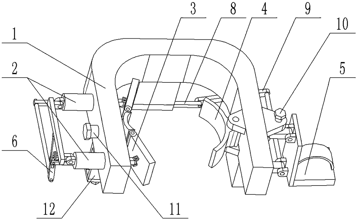
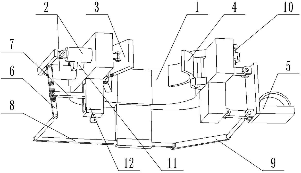
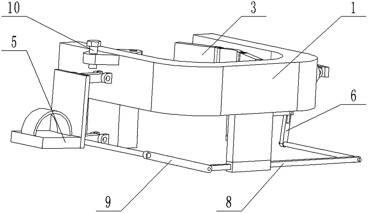
[0037] Combine below Figure 1-11 In this embodiment, a foot buckle that can automatically reduce diameter includes a U-shaped frame 1, a pressing plate frame 2, a pressing plate 3, an arc-shaped plate 4, a pedal assembly 5, a linkage lever 6, a fulcrum rod 7, and a connecting rod I8. , Connecting rod Ⅱ 9 and fulcrum rod carriage 12, the pressure plate frame 2 is slidably connected to the left end of the U-shaped frame 1, the pressure plate 3 is hingedly connected to the right end of the pressure plate frame 2, the pressure plate 3 is located on the inner side of the U-shaped frame 1, and the arc plate 4 is hingedly connected to the inner side of the right end of the U-shaped frame 1, the foot pedal assembly 5 is hingedly connected to the outer side of the right end of the U-shaped frame 1, the foot pedal assembly 5 is hingedly connected to one end of the connecting rod Ⅱ9, and the other end of the connecting rod Ⅱ9 is connected to the connecting rod Ⅰ8 One end of the connectin...
specific Embodiment approach 2
[0040] Combine below Figure 1-11 This embodiment will be described. This embodiment will further explain the first embodiment. The U-shaped frame 1 includes a U-shaped frame body 1-1, a connecting rod sliding frame 1-2, a connecting rod insertion hole 1-3, and a telescopic shaft hole 1. -4. The limit plate 1-5 and the arc-shaped plate mounting frame 1-6, the lower end of the rear end of the U-shaped frame body 1-1 is fixedly connected to the connecting rod sliding frame 1-2, and the lower end of the connecting rod sliding frame 1-2 is provided The connecting rod socket 1-3, the left end of the U-shaped frame body 1-1 is provided with two telescopic shaft holes 1-4 and an adjusting threaded through hole I, the adjusting threaded through hole I is located between the two telescopic shaft holes 1-4 , The inner side of the right end of the U-shaped frame body 1-1 is fixedly connected with an arc-shaped plate mounting frame 1-6, and the outer side of the right end of the U-shaped f...
specific Embodiment approach 3
[0041] Combine below Figure 1-11 This embodiment will be described. This embodiment will further explain the second embodiment. The platen frame 2 includes a telescopic shaft I2-1, a telescopic shaft II2-2 and a telescopic shaft bracket 2-3, a telescopic shaft I2-1 and a telescopic shaft II2 -2 are hinged on both ends of the telescopic shaft frame 2-3, respectively, the telescopic shaft Ⅰ2-1 and the telescopic shaft Ⅱ 2-2 are slidably connected in the two telescopic shaft holes 1-4; when in use, the left and right movement of the pressure plate frame 2 increases Increase or decrease the distance between the pressing plate 3 and the arc-shaped plate 4.
PUM
 Abstract
Description
Claims
Application Information
 - R&D
- Intellectual Property
- Life Sciences
- Materials
- Tech Scout
- Unparalleled Data Quality
- Higher Quality Content
- 60% Fewer Hallucinations
Browse by: Latest US Patents, China's latest patents, Technical Efficacy Thesaurus, Application Domain, Technology Topic, Popular Technical Reports.
© 2025 PatSnap. All rights reserved.Legal|Privacy policy|Modern Slavery Act Transparency Statement|Sitemap|About US| Contact US: help@patsnap.com


