
Continuous perforating machine

A technology of punching machine and punching head, which is applied in the field of punching machines, can solve problems such as troublesome operation, complex structure, and low punching efficiency, and achieve the effects of convenient operation and improved work efficiency

Inactive Publication Date: 2017-12-12
肇庆高新区异星科技有限公司
View PDF0 Cites 8 Cited by
  • Summary
  • Abstract
  • Description
  • Claims
  • Application Information

AI Technical Summary

Problems solved by technology

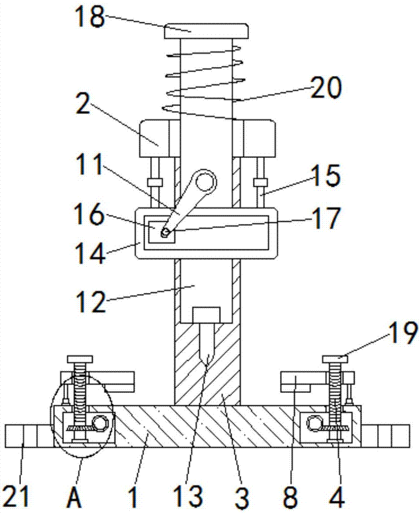
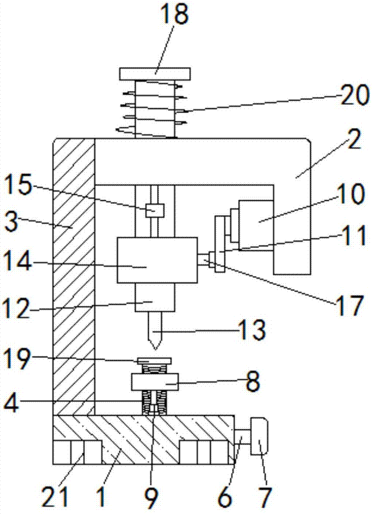
[0003] The purpose of the present invention is to solve the problem that the structure of the object punching machine in the prior art is relatively complicated, the operation is more troublesome and the punching efficiency is low when punching the object, and a continuous punching machine is proposed.

Method used


Image

  • Continuous perforating machine
  • Continuous perforating machine
  • Continuous perforating machine

Examples


Embodiment Construction

[0017] The following will clearly and completely describe the technical solutions in the embodiments of the present invention with reference to the accompanying drawings in the embodiments of the present invention. Obviously, the described embodiments are only some, not all, embodiments of the present invention.

[0018] In describing the present invention, it should be understood that the terms "upper", "lower", "front", "rear", "left", "right", "top", "bottom", "inner", " The orientation or positional relationship indicated by "outside", etc. is based on the orientation or positional relationship shown in the drawings, and is only for the convenience of describing the present invention and simplifying the description, rather than indicating or implying that the referred device or element must have a specific orientation, so as to Specific orientation configurations and operations, therefore, are not to be construed as limitations on the invention.

[0019] refer to Figure ...


PUM


Abstract

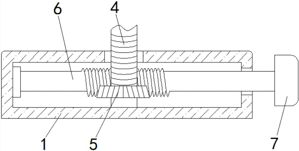
The invention discloses a continuous punching machine, which comprises a base and an upper shelf plate arranged in parallel, the upper shelf plate is arranged above the base, the top of the upper shelf plate and the base are fixedly connected by a support column, and the base There are two symmetrically arranged two cavities at both ends of the cavity, and a threaded rod is connected to the cavity for rotation, and a gear is fixedly sleeved on the threaded rod, and a worm meshed with the gear is connected to the cavity for rotation, One end of the worm runs through the inner wall of the cavity and is fixedly connected with a handle, the end of the threaded rod away from the gear runs through the inner top of the cavity and extends outward, and the extended end of the threaded rod is threaded with an extrusion plate, The ends of the two extruding plates that are far away from each other are connected to the top of the base through telescopic rods. The present invention makes the device more convenient for workers to operate the punching mechanism through the arrangement of mechanisms such as extrusion plates and load-bearing rods, thereby improving the work efficiency of workers.

Description

technical field [0001] The invention relates to the technical field of punching machines, in particular to a continuous punching machine. Background technique [0002] The punching machine is composed of four parts that cooperate with each other to complete the punching process. First, the material is moved to the scanning area of ​​the camera of the automatic punching machine. After the camera scans the image, it processes and sends a signal to the control part. After the control part receives the signal, further Process and control the movement of the transmission part, so that the punch moves on the X-axis and Y-axis on the plane. After the movement is completed, the pneumatic part starts to work, and the solenoid valve controls the cylinder to perform the punching action. However, the structure of the existing object punching machine is comparatively complicated, and when the object is punched, the operation is relatively troublesome, the punching efficiency is low, and ...

Claims


Application Information

Patent Timeline
Patent Type & Authority Applications(China)
IPC IPC(8): B30B1/10B21D28/24B21D43/00
CPCB30B1/10B21D28/24B21D43/003
Inventor 不公告发明人
Owner 肇庆高新区异星科技有限公司
Learn More