
Novel floor-drain drainage inner core and floor drain with inner core

A technology of inner core and floor drain, which is applied to drainage structures, water supply devices, waterway systems, etc., and can solve problems such as air leakage, spring loss of elasticity, and inability to increase drainage speed

Pending Publication Date: 2017-12-12
爱朗特厨卫有限公司
View PDF5 Cites 9 Cited by
  • Summary
  • Abstract
  • Description
  • Claims
  • Application Information

AI Technical Summary

Problems solved by technology

[0002] Floor drains are usually used in indoor bathrooms, kitchens and other wading floor drainage. At present, the common floor drains in daily life are mostly ordinary floor drains, which have a floor drain body and a filter cover. There is an anti-odor cover in the water storage tank to achieve the anti-odor effect. There is also a floor drain whose structure includes the main body of the floor drain and movable water sealing parts. And opening the through hole can drain water. The function of the water sealing part is to prevent the gas from the sewer pipe from being discharged through the floor drain, which will cause odor to pollute the air. Therefore, it is necessary to block the through hole when the water is not drained, and the water sealing part is activated by magnetic Attract or repel each other to realize the floor drain of blocking the through hole or opening the through hole of the water sealing part. It can realize the automatic opening and closing of the water sealing part through the drainage gravity. In addition, the spring replaces the magnet to achieve the same effect, but the spring is easy Losing the elasticity will not achieve the effect, and the floor drain is prone to leaking water sealing parts after a period of use due to structural inadequacies, resulting in air leakage and no deodorization
[0003] Although the above-mentioned floor drains and other existing floor drains have different anti-odor structures, what they have in common is that the drainage speed cannot be improved, and the drainage flow rate of the size of the floor drain itself is fixed. water

Method used


Image

  • Novel floor-drain drainage inner core and floor drain with inner core

Examples


Embodiment Construction

[0024] In order to further explain the technical solution of the present invention, the present invention will be described in detail below through a specific embodiment.

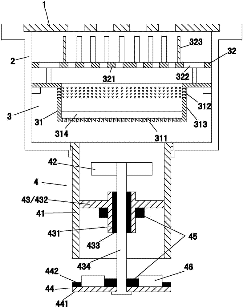
[0025] A new type of floor drain disclosed in this embodiment is usually used in floor drainage for wading water such as indoor toilets and kitchens, such as figure 1 As shown, it includes a filter cover plate 1, a floor drain housing 2, a filter device 3 and a drainage inner core 4. The connection position relationship of each part will be described in detail below with reference to the drawings.

[0026] The floor drain housing 2 has a water inlet port and a water outlet port, and the filter cover 1 is arranged on the water inlet port of the floor drain housing 2 .

[0027] The drainage inner core 4 includes an inner core body 41 having a water inlet port and a water outlet port and a drainage impeller 42 rotatably arranged in the inner core body 41 to accelerate drainage, and the water inlet port of the ...


PUM


Abstract

The invention discloses a novel floor-drain drainage inner core and a floor drain with the inner core. The drainage inner core comprises an inner core body with a water inlet and a water outlet and a drainage impeller which is rotatably arranged in the inner core body and can be used for drain water in an accelerated mode, and water flow is driven by the rotation of the drainage impeller; the floor drain comprises the drainage inner core and a floor drain shell with a water inlet and a water outlet, the water inlet of the drainage inner core is connected with the water outlet of the floor drain shell, and the water inlet of the floor drain shell is provided with a filtration cover plate. The drainage inner core of the structure can increase the drainage speed through the rotation of the drainage impeller, the drainage is smooth, and the effect is good.

Description

technical field [0001] The invention relates to the field of floor drains, in particular to a floor drain with an accelerated drainage structure. Background technique [0002] Floor drains are usually used in indoor bathrooms, kitchens and other wading floor drainage. At present, the common floor drains in daily life are mostly ordinary floor drains, which have a floor drain body and a filter cover. There is an anti-odor cover in the water storage tank to achieve the anti-odor effect. There is also a floor drain whose structure includes the main body of the floor drain and a movable water sealing part. And open the through hole to drain water. The function of the water sealing part is to prevent the gas from the sewer pipe from being discharged through the floor drain, which will cause odor to pollute the air. Therefore, it is necessary to block the through hole when the water is not drained. Attract or repel each other to realize the floor drain of blocking the through hol...

Claims


Application Information

Patent Timeline
IPC IPC(8): E03F5/04E03F5/06E03F5/14
CPCE03F5/0407E03F5/041E03F5/06E03F5/14E03F2005/0417
Inventor 陈奕彦
Owner 爱朗特厨卫有限公司
Learn More