
Manufacturing method of bases for installation of speed reducers and bases for installation of speed reducers

A manufacturing method and reducer technology, applied in the direction of engine base, supporting machine, mechanical equipment, etc., can solve the problems of high cost and complicated manufacturing process, and achieve the effect of low cost and simple process

Active Publication Date: 2017-12-12
NABLESCO CORP
View PDF8 Cites 0 Cited by
  • Summary
  • Abstract
  • Description
  • Claims
  • Application Information

AI Technical Summary

Problems solved by technology

As a result, the manufacturing process is complicated and the cost is high

Method used


Image

  • Manufacturing method of bases for installation of speed reducers and bases for installation of speed reducers
  • Manufacturing method of bases for installation of speed reducers and bases for installation of speed reducers
  • Manufacturing method of bases for installation of speed reducers and bases for installation of speed reducers

Examples


Embodiment Construction

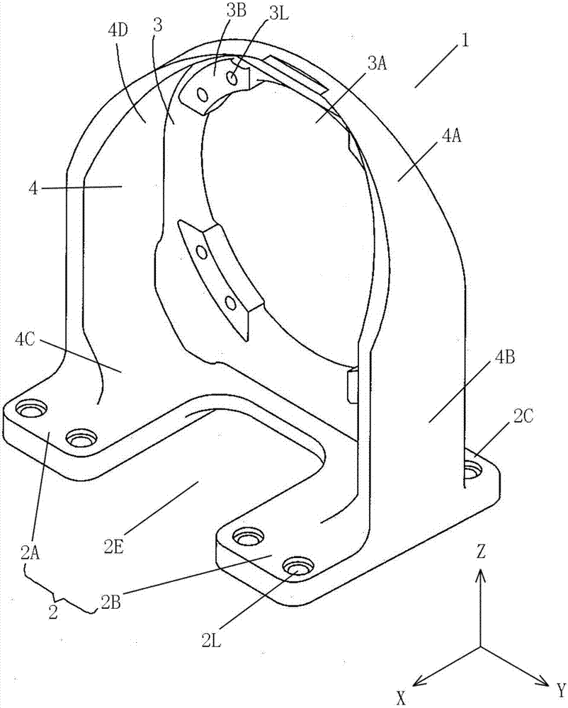
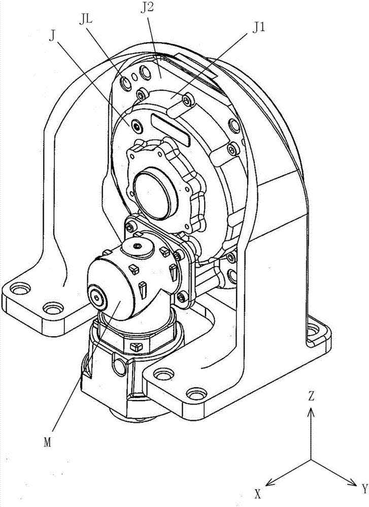
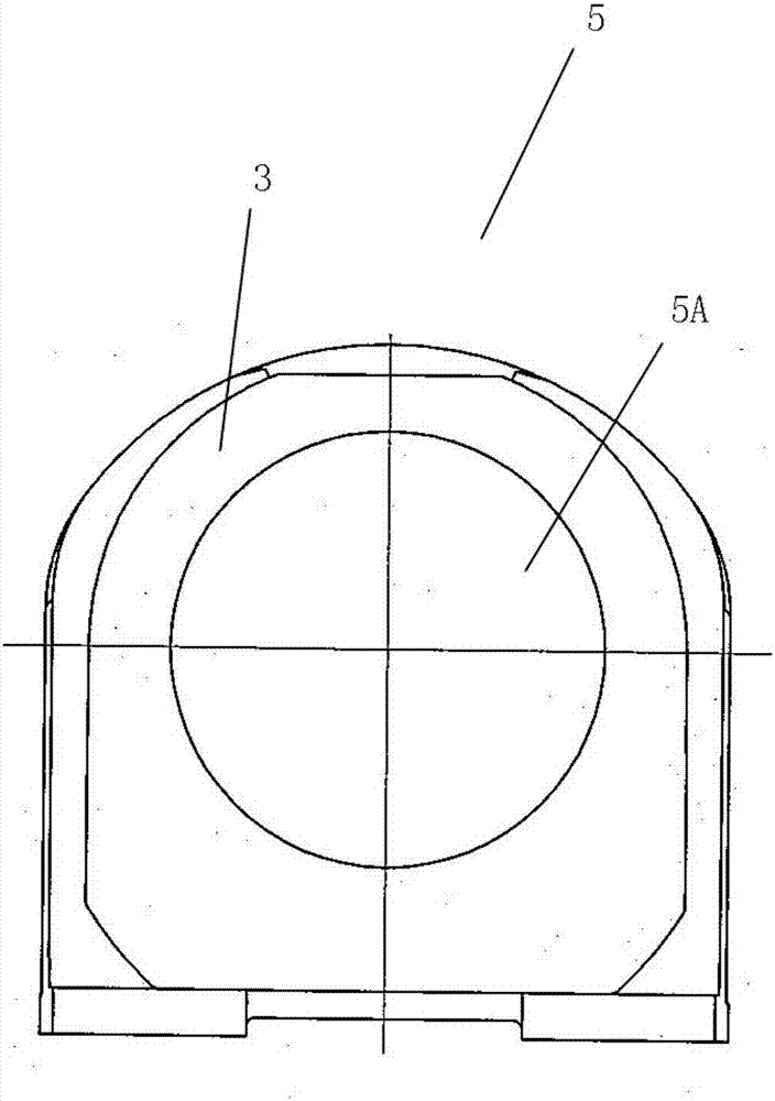
[0022] Hereinafter, the manufacturing method of the base for attachment of the reduction gear of this invention is demonstrated, referring drawings. figure 1 It is a schematic diagram showing an example of the reducer mounting base of the present invention. figure 2 A schematic diagram showing an example of assembling a reducer, a motor, and a reducer mounting base. image 3 A schematic diagram showing a reducer mounting base manufactured by the blank manufacturing process. Figure 4 A schematic diagram showing the base for mounting the reducer corresponding to the reducer of the first specification. Figure 5 A schematic diagram showing a reducer mounting base for a reducer corresponding to the second specification.

[0023] refer to figure 1 An example of the reducer mounting base of the present invention will be described.

[0024] The base 1 for installing the reducer is made of a metal material with high strength. Such as figure 1 As shown, the reducer mounting ...


PUM


Abstract

The invention provides a manufacturing method of bases for installation of speed reducers. The manufacturing method is used for manufacturing the different specifications of bases which can be provided with the speed reducers of different specifications and used for installation of the bases, and the radial dimensions of the speed reducers of the different specifications are different from one another. The manufacturing method at least comprises the following steps that a blank is manufactured, specifically, the blank at least comprises a bottom plate part used for installing the corresponding base for installation of the corresponding speed reducer on a using object, an installation part which is perpendicular to the bottom plate part and is erected in a plate mode, a through hole parallel to the bottom plate part is formed in the installation part in a penetrating mode, and the diameter of the through hole is smaller than or equal to the smallest radial direction of the corresponding speed reducer among the speed reducers of different specifications; and broaching is conducted, specifically, the through hole is broached according to the specification of the speed reducer to be installed so that a through part can be formed. According to the manufacturing method, the bases which can be provided with the speed reducers of different specifications and are of different specifications can be manufactured through the simple procedures and low cost.

Description

technical field [0001] The invention relates to a manufacturing method of a base for installing a reducer and a base for installing the reducer. Background technique [0002] It is known that there is a speed reducer that plays the role of matching speed and transmitting torque between the prime mover and the working machine or the actuator. In detail, it uses the transmission ratio of the gear to convert the speed, decelerates the motor, internal combustion engine or other high-speed running power to the required speed, and obtains a larger torque. Such a speed reducer has a cylindrical appearance, a radial flange portion is provided on the outer periphery thereof so as to protrude radially outward, and mounting holes are provided at intervals in the circumferential direction on the radial flange portion. [0003] Such a reducer is usually mounted on a reducer mounting base for support. The base for mounting the reducer usually includes at least a bottom plate for fixing ...

Claims


Application Information

Patent Timeline
IPC IPC(8): F16M5/00
CPCF16M5/00
Inventor 中村江児沖村隆行
Owner NABLESCO CORP
Features
  • Generate Ideas
  • Intellectual Property
  • Life Sciences
  • Materials
  • Tech Scout
  • Unparalleled Data Quality
  • Higher Quality Content
  • 60% Fewer Hallucinations
Learn More