A laser distance measuring sensor calibration method

A technology of laser ranging and calibration method, applied in the field of robot calibration, to achieve the effect of accurate calibration results

Inactive Publication Date: 2017-12-12
BEIHANG UNIV
View PDF8 Cites 29 Cited by
  • Summary
  • Abstract
  • Description
  • Claims
  • Application Information

AI Technical Summary

Problems solved by technology

However, due to processing and installation errors, it is necessary to calibrate the installation position of the sensor to ensure the accuracy of sensor normal measurement

Method used


Image

  • A laser distance measuring sensor calibration method
  • A laser distance measuring sensor calibration method
  • A laser distance measuring sensor calibration method

Examples


Embodiment Construction

[0037] The technical solutions of the present invention will be clearly and completely described below in conjunction with the accompanying drawings. Apparently, the described embodiments are some of the embodiments of the present invention, but not all of them. Based on the embodiments of the present invention, all other embodiments obtained by persons of ordinary skill in the art without making creative efforts fall within the protection scope of the present invention.

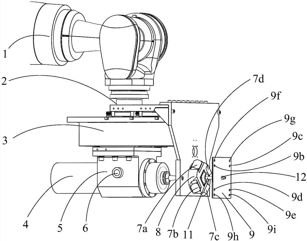
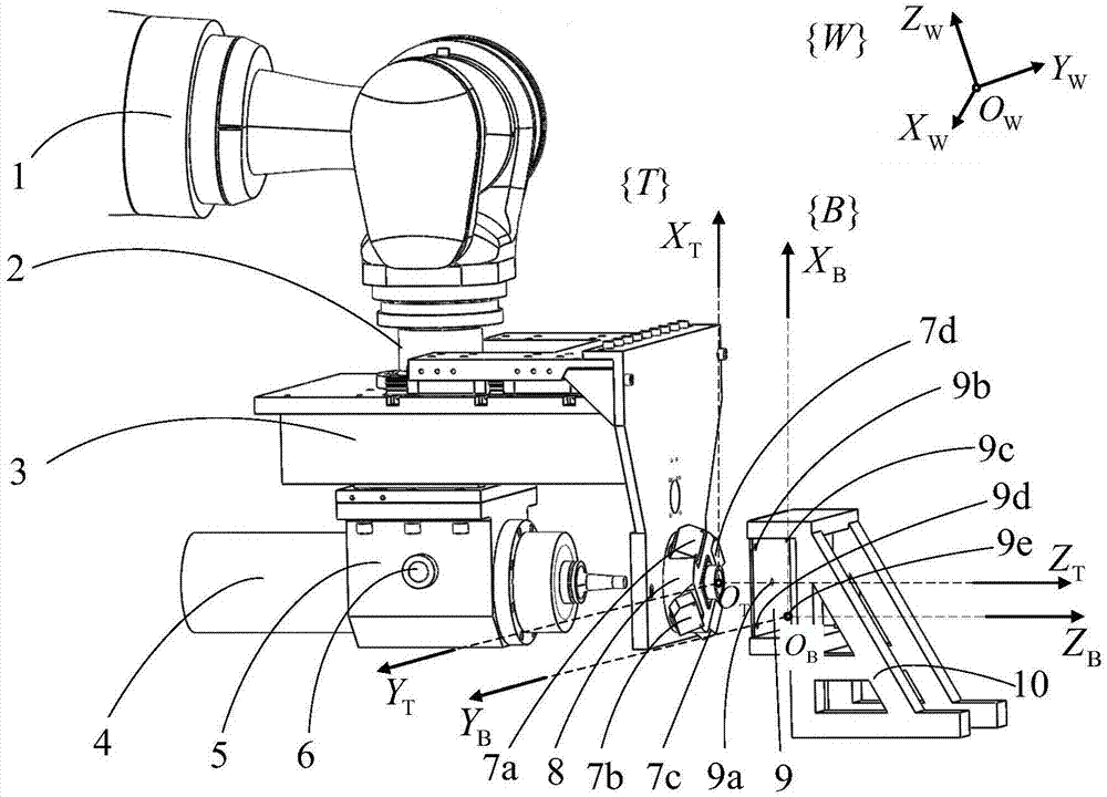
[0038] see figure 1 and figure 2As shown, the device used in the method of the present invention includes a laser tracker, an industrial mechanical arm 1, a flange 2, a hole-making end effector, a calibration rod 11, a plane calibration plate 9 and a mounting frame 10, wherein the hole-making end effector It mainly includes a feed module 3, an electric spindle 4, an electric spindle mounting seat 5, a large target ball seat 6, a small target ball seat 12, a pressing head 8, and four laser distance measurin...


PUM


Abstract

The invention provides a laser distance measuring sensor calibration method and belongs to the field of robot calibration. Devices employed by the method include a laser tracker, an industrial mechanical arm, a flange plate, a hole making end effector, a calibration rod, a planar calibration plate and an installing rack. The hole making end effector mainly comprises a feeding module, an electric spindle, an electric spindle installing base, a big target ball seat, a small target ball seat, a pressing head and four laser distance measuring sensors. The method comprises the steps of firstly calibrating an included angle between a laser beam and an electric spindle feeding direction; building a tool coordinate system and a work piece coordinate system by means of the laser tracker and moving the hole making end effector to a place in front of the planar calibration plate and performing rotation for multiple times; calculating the coordinates under the coordinate systems in different states of each laser point according to geometrical relationships, transforming the coordinates of all the points to the same coordinate system and obtaining a space equation of the laser beam through fitting. The method can calibrate transmitting point positions and laser beam vector orientations of laser distance measuring sensors and make normal detection results more accurate.

Description

technical field [0001] The invention relates to the field of robot calibration, in particular to a calibration method for a laser range-finding sensor, which can calibrate the positions of emission points and the sagittal directions of laser beams of four installed laser range-finding sensors. Background technique [0002] With the continuous improvement of people's material and cultural living standards, the way of travel is gradually changing, and more and more people choose to travel by air, so the demand for aircraft is increasing day by day. Automatic hole making is the most critical link in the manufacture and assembly of large aircraft, and occupies a very important position in aircraft manufacturing. The main connection method used in aircraft structures is mechanical connection. The most common connection method is riveting. The first step in riveting is drilling. The size of the hole and the quality of the hole wall seriously affect the strength of the riveting sea...

Claims


Application Information

Patent Timeline
Patent Type & Authority Applications(China)
IPC IPC(8): G01S7/497
CPCG01S7/497
Inventor 袁培江曹双倩陈冬冬蔡鹦纪小男高雷苏峰
Owner BEIHANG UNIV
Why Eureka
Try Eureka