Numerical simulation analysis method for microwave field chaotic stirrer

A numerical simulation and analysis method technology, applied in design optimization/simulation, instrumentation, electrical digital data processing, etc., can solve problems such as grid deformation, exceeding the scope of application, difficult numerical simulation, etc.

Inactive Publication Date: 2017-12-12
SICHUAN UNIV
View PDF3 Cites 8 Cited by
  • Summary
  • Abstract
  • Description
  • Claims
  • Application Information

AI Technical Summary

Problems solved by technology

[0006] However, for the non-fixed microwave field stirrer, the stirring part is not fixed, so that not only the moving object is contained in the microwave cavity, but also the motion of the object has uncertainty, which has exceeded the above-mentioned method of moments and time domain The scope of application of the finite difference method; in addition, because the grid

Method used


Image

  • Numerical simulation analysis method for microwave field chaotic stirrer
  • Numerical simulation analysis method for microwave field chaotic stirrer
  • Numerical simulation analysis method for microwave field chaotic stirrer

Examples


Embodiment 1

[0056] In this embodiment, the stirrer provided with a non-fixed metal stirring rod is used as a microwave field chaos stirrer, wherein the non-fixed metal stirring rod is used as a stirring component. What needs to be obtained in this embodiment is the dynamic electromagnetic field distribution in the stirrer cavity. The specific process includes The following steps:

[0057] (1) Establish the finite element model of the microwave field chaos stirrer, which specifically includes the following sub-steps,

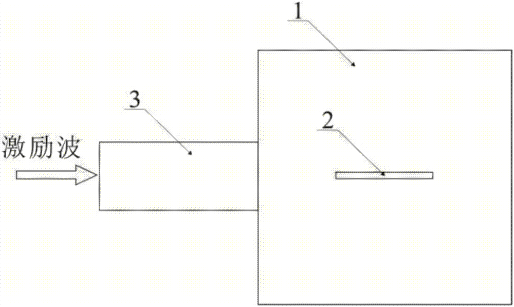
[0058] 1) Directly draw the two-dimensional geometric model of the microwave field chaos stirrer in the finite element analysis software, such as figure 1 As shown, the geometric model includes a microwave cavity 1, a metal stirring rod 2 is designed in the microwave cavity 1, and a rectangular waveguide 3 is located on one side of the microwave cavity 1; the geometry of the microwave cavity 1 and the metal stirring rod 2 is Coordinate origin (0, 0), the side length dimensi...

Embodiment 2

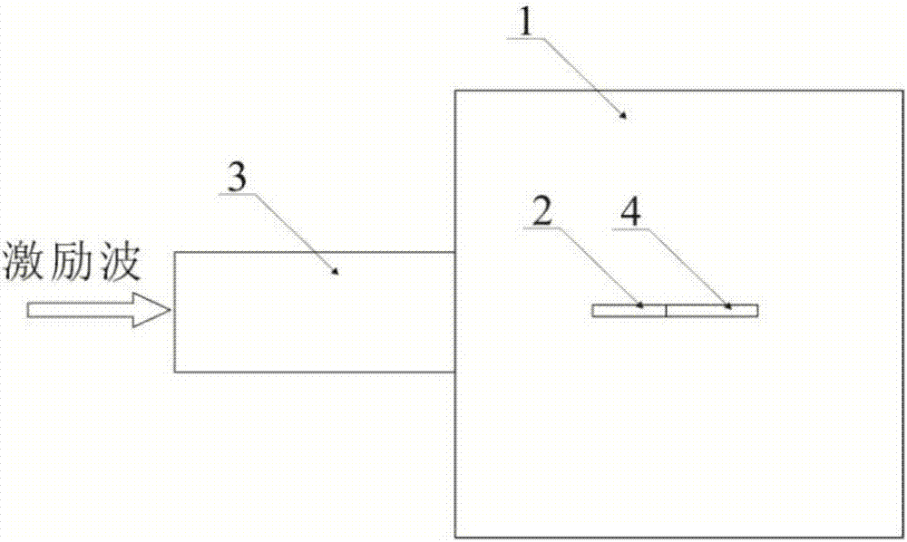
[0082] In this embodiment, the stirrer provided with a non-fixed metal stirring rod 2 and a metal flexible ribbon 4 connected to the metal stirring rod 2 is a microwave field chaos stirrer, wherein the non-fixed metal stirring rod 2 and the metal stirring rod 2 are connected The metal flexible ribbon 4 is used as the stirring member. What this embodiment needs to obtain is the dynamic electromagnetic field distribution in the stirrer cavity. The specific process includes the following steps:

[0083] (1) Establish the finite element model of the microwave field chaos stirrer, which specifically includes the following sub-steps,

[0084] 1) Directly draw the two-dimensional geometric model of the microwave field chaos stirrer in the finite element analysis software, such as figure 2 As shown, the geometric model includes a microwave cavity 1, a metal stirring rod 2 and a metal flexible ribbon 4 connected to the metal stirring rod 2 are designed in the microwave cavity 1, and a...


PUM


Abstract

The invention discloses a numerical simulation analysis method for a microwave field chaotic stirrer. The method comprises the steps of firstly building a finite element model of the microwave field chaotic stirrer and a random motion function model of a stirring part in the microwave field chaotic stirrer; secondly defining a control equation and a boundary constraint equation of a geometric model region of the microwave field chaotic stirrer; and thirdly solving the control equation by utilizing a finite element method to obtain electromagnetic field distribution in the microwave field chaotic stirrer. According to the method, the random motion function model is combined with the finite element model; a random motion of the non fixed stirring part in the microwave field chaotic stirrer is simulated by utilizing the random function model to obtain a moving mesh changed with the stirring part; and a partial differential equation of an electromagnetic field is solved by utilizing the finite element method, so that dynamic electromagnetic field distribution, changed with time, of the microwave field chaotic stirrer can be obtained.

Description

technical field [0001] The invention belongs to the technical field of computer data processing, and relates to a numerical simulation analysis of an electromagnetic field, in particular to a numerical simulation analysis method of a microwave field chaos stirrer applied to a microwave oven. Background technique [0002] With the progress of society and the development of microwave energy utilization technology, the use of microwave ovens is becoming more and more popular. Due to the good penetrability of the microwave, energy can be directly sent into the inside of the object to be heated, and the inside and outside of the object can be heated at the same time, thereby greatly shortening the heating time and improving the heating efficiency. However, due to the unevenness of microwave heating, there will be overcooked and undercooked areas inside the food, resulting in food that cannot be eaten safely, thereby restricting the effective application of microwave energy. Ther...

Claims


Application Information

Patent Timeline
IPC IPC(8): G06F17/50
CPCG06F30/20
Inventor 杨晓庆周杰吴诗月
Owner SICHUAN UNIV
Why Eureka
Try Eureka