Supercharge Your Innovation With Domain-Expert AI Agents!

winding spindle

A spindle and winding machine technology, applied in the direction of thin material handling, delivery of filamentous materials, transportation and packaging, etc., can solve the problems of complex and impossible assembly capacity

Active Publication Date: 2021-05-11
OERLIKON TEXTILE GMBH & CO KG
View PDF13 Cites 0 Cited by
  • Summary
  • Abstract
  • Description
  • Claims
  • Application Information

AI Technical Summary

Problems solved by technology

[0005] A further disadvantage of the winding spindles known from the prior art is that, with the chuck protruding considerably, the assembly capability is very complicated or almost impossible

Method used


Image

  • winding spindle
  • winding spindle
  • winding spindle

Examples


Embodiment Construction

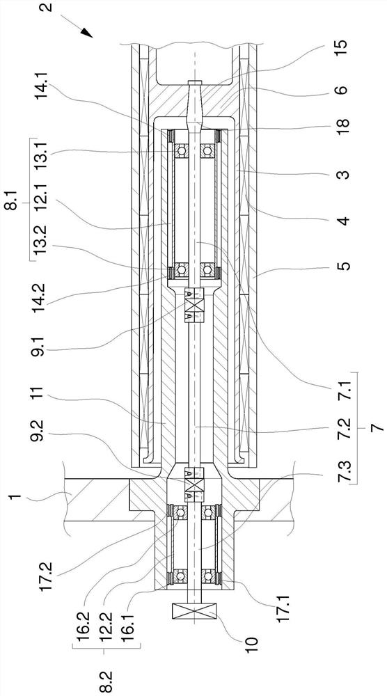
[0026] exist figure 1 A longitudinal section of a first exemplary embodiment of a winding spindle is schematically shown in partial view in . The winding spindle 2 is held on the spindle support 1 by means of a hollow support 11 . The winding spindle 2 on the spindle support 1 has a large number of protruding chucks 3 which are configured as hollow cylinders at both ends. The free end of chuck 3 is not in figure 1 shown in , because no components relevant to the present invention are included in this free end. The free end of the chuck 3 is usually sealed by a cover.

[0027] The opposite open end of the chuck 3 facing the spindle support 2 is intended to receive a drive shaft 7 which is connected to the hub 6 of the chuck 3 by means of a shaft-hub connection 15 . The hub connection 15 is formed between the hub 6 and a shoulder 18 of the front bearing shaft 7.1 which increases the thickness of said front bearing shaft 7.1.

[0028] The drive shaft 7 is formed by a bearing...


PUM


Abstract

The invention relates to a winding spindle for winding wire in a winding machine. For this purpose, the winding spindle has long projecting chucks for receiving a plurality of winding bobbins, wherein said chucks can be driven by means of a multi-part drive shaft mounted in a hollow support. The drive shaft has a rear bearing shaft, an intermediate shaft and a front bearing shaft, wherein the front bearing shaft is connected to the chuck in a non-rotatable manner relative to the chuck, and wherein the rear bearing shaft is connected to the driver . The bearing shaft and the intermediate shaft are elastically connected to each other through a front coupling and a rear coupling. In order to achieve adjustability and ease of installation, according to the invention, the front coupling and / or the rear coupling are fastened to the shaft ends of the bearing shaft and the intermediate shaft by means of a plurality of clamping elements .

Description

technical field [0001] The present invention relates to a winding spindle for winding wire to form a plurality of bobbins. Background technique [0002] A winding spindle of a general type is known from DE 2 261 709 A1. [0003] Such known winding spindles are used in winding machines for winding a plurality of wires in parallel to form bobbins. For this purpose, the winding spindle is arranged projecting on the spindle support, wherein the projecting portion of the winding spindle is configured as a chuck for receiving and securing the winding tube. The chuck is embodied as a hollow cylinder and is connected via a hub to a drive shaft arranged in the interior of the winding spindle. The drive shaft is mounted rotatably in a hollow cylindrical support that protrudes into the interior of the chuck. [0004] To receive a plurality of bobbins, a correspondingly large number of protruding chucks is required, so that the drive shaft must have a relatively large length in order...

Claims


Application Information

Patent Timeline
Patent Type & Authority Patents(China)
IPC IPC(8): B65H54/547
CPCB65H54/547B65H2701/31
Inventor H·瓦尔特曼J·科瓦尔斯基
Owner OERLIKON TEXTILE GMBH & CO KG
Features
  • R&D
  • Intellectual Property
  • Life Sciences
  • Materials
  • Tech Scout
  • Unparalleled Data Quality
  • Higher Quality Content
  • 60% Fewer Hallucinations
Learn More