
Magnetic separator

A magnetic separator and magnet technology, applied in the field of magnetic separators, can solve the problems of easy congestion of raw materials, damage to processing equipment, incomplete screening, etc., and achieve the effect of stabilizing and fixing the screening device.

Inactive Publication Date: 2017-12-15
刘汪钊
View PDF1 Cites 0 Cited by
  • Summary
  • Abstract
  • Description
  • Claims
  • Application Information

AI Technical Summary

Problems solved by technology

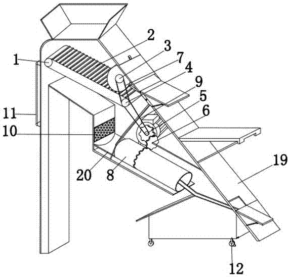
[0002] Raw materials are usually mixed with magnetic metal impurities such as iron, which need to be removed by a magnetic separator to avoid damage to subsequent processing equipment and affect the quality of raw materials. For example, the invention patent with application number 201520837126.4 includes a material cylinder, which is set There is a screw, one end of the material cylinder is provided with a material inlet, and the other end is provided with a material outlet. The position of the material cylinder close to the inner wall of the material cylinder is arranged in parallel along the axial direction with multiple driven wheels, and the outside of the material cylinder is arranged in parallel along the axial direction. A driving wheel, a conveyor belt is wound between the driven wheel and the driving wheel, a channel for the conveyor belt to pass through is arranged on the wall of the material cylinder, and a plurality of permanent magnets are arranged at intervals along the length direction of the conveyor belt on the conveyor belt. Although this patent It can improve the efficiency of magnetic separation, but the raw materials are easy to be congested and the screening is not thorough

Method used


Image

  • Magnetic separator
  • Magnetic separator
  • Magnetic separator

Examples


Embodiment Construction

[0014] The technical solutions in the embodiments of the present invention will be clearly and completely described below with reference to the accompanying drawings in the embodiments of the present invention. Obviously, the described embodiments are only a part of the embodiments of the present invention, but not all of the embodiments. Based on the embodiments of the present invention, all other embodiments obtained by those of ordinary skill in the art without creative efforts shall fall within the protection scope of the present invention.

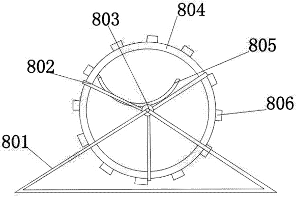
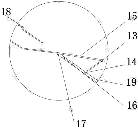
[0015] see Figure 1-3 , The present invention provides a technical solution: a magnetic separator, comprising a magnet roller 3 and a housing 19, the upper end of the housing 19 is installed with a magnet roller 3, the lower side of the magnet roller 3 is provided with a crawler 2, and the magnet roller 3 The magnetic material with larger volume and stronger adsorption capacity is adsorbed on the upper surface, and the first screenin...


PUM


Abstract

The invention discloses a magnetic separator, which comprises a magnet roller and a casing. A magnet roller is installed on the inner wall of the upper end of the casing, and crawlers are arranged on the lower side of the magnet roller. The magnet roller passes through a first belt and a second roller. The right side of the second roller is provided with a crawler belt, the second roller is connected with the first roller through the crawler belt, the second roller is connected with the engine through the second belt, and a gear is installed on the right side of the lower end of the engine , a screening device is installed at the lower end of the gear. The magnetic separator, through the cooperation of the first roller and the track, through the cooperation of the second roller and the track, can achieve the benefit of uniform falling of raw materials, through the cooperation of the track and the magnet roller, the benefit of the first screening can be achieved, and through the cooperation of the engine and the gear , Through the cooperation of the gear and the screening device, the benefits of secondary screening of raw materials are achieved, and through the cooperation of the bracket and the fixed rod, the benefits of stably fixing the screening device are achieved.

Description

technical field [0001] The invention relates to the technical field of magnetic separators, in particular to a magnetic separator. Background technique [0002] The raw materials are usually mixed with iron and other magnetic metal impurities, which need to be removed by a magnetic separator, so as not to damage the subsequent processing equipment and affect the quality of the raw materials, such as the invention patent with the application number of 201520837126.4, including the material barrel, which is set inside the material barrel. There is a screw, one end of the material barrel is provided with a feeding port, and the other end is provided with a discharging port, a plurality of driven wheels are arranged in parallel along the axial direction in the position of the material barrel near the inner wall of the material barrel, and many driven wheels are arranged in parallel along the axial direction outside the material barrel. A driving wheel, a conveyor belt is wound b...

Claims


Application Information

Patent Timeline
Patent Type & Authority Applications(China)
IPC IPC(8): B03C1/18
CPCB03C1/18
Inventor 刘汪钊
Owner 刘汪钊
Learn More