Manufacturing method of circular tube through box girder steel member and its steel member structure

A manufacturing method and technology of steel components, applied in the direction of manufacturing tools, welding equipment, arc welding equipment, etc., can solve problems such as difficulty in adapting to the diversified development of structural components, affecting the safety of building structures, and unscientific manufacturing methods, etc., to achieve shortening The effect of production cycle, good operability, and convenient processing and production

Active Publication Date: 2019-09-10
湖北精工工业建筑系统有限公司
View PDF7 Cites 0 Cited by
  • Summary
  • Abstract
  • Description
  • Claims
  • Application Information

AI Technical Summary

Problems solved by technology

[0003] In the field of building steel structure in my country, the beam-column connection of the main structure of the building usually adopts the method of breaking the steel beam through the column; with the maturity of the technology in the field of steel structure processing in my country and the rapid development of the industry, the beam-column connection is simply connected with the column-through beam It is difficult to meet the needs of the diversified development of structural components; in addition, in the design of stadium structures, some structures are considered in terms of force, and beams passing through steel columns are more beneficial to the structure; circular tubes passing through box girder steel components are not Like other conventional steel structural components, there are relatively mature processing and manufacturing techniques; however, circular tube through box girder steel components usually exist in the joint area with the building structure. If the manufacturing method is unscientific and unreasonable, it will affect the structure of the entire building safety

Method used


Image

  • Manufacturing method of circular tube through box girder steel member and its steel member structure
  • Manufacturing method of circular tube through box girder steel member and its steel member structure
  • Manufacturing method of circular tube through box girder steel member and its steel member structure

Examples


Embodiment Construction

[0040] The implementation of the present invention will be described in detail below in conjunction with the accompanying drawings, but they do not constitute a limitation to the present invention, and are only examples. At the same time, the advantages of the present invention are clearer and easier to understand through the description.

[0041] Referring to the accompanying drawings, it can be seen that the manufacturing method of the circular tube penetrating box girder steel member is characterized in that it comprises the following steps:

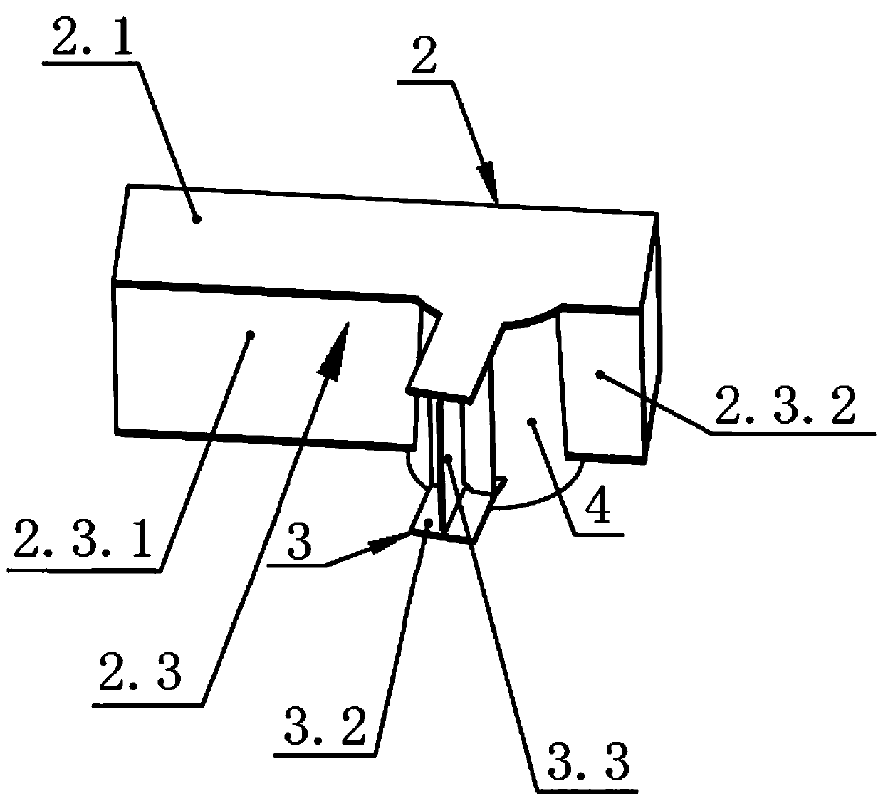
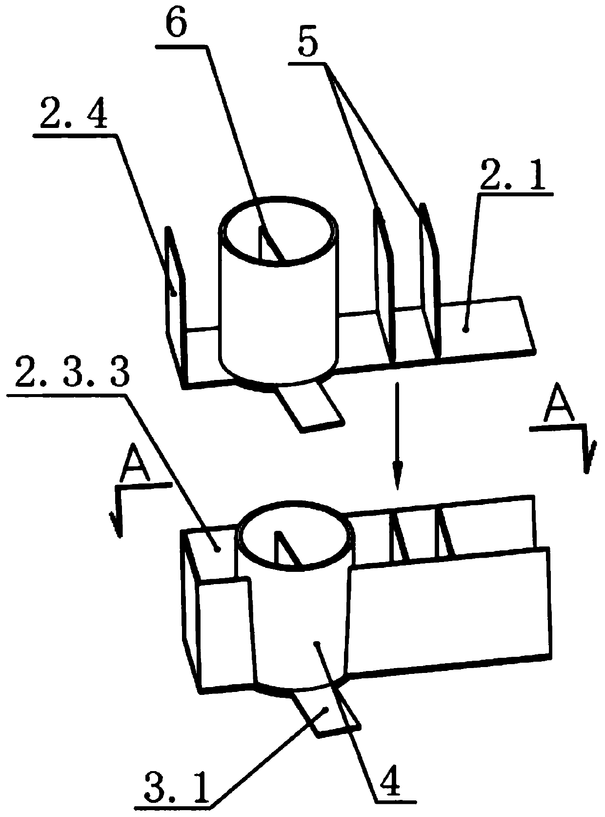
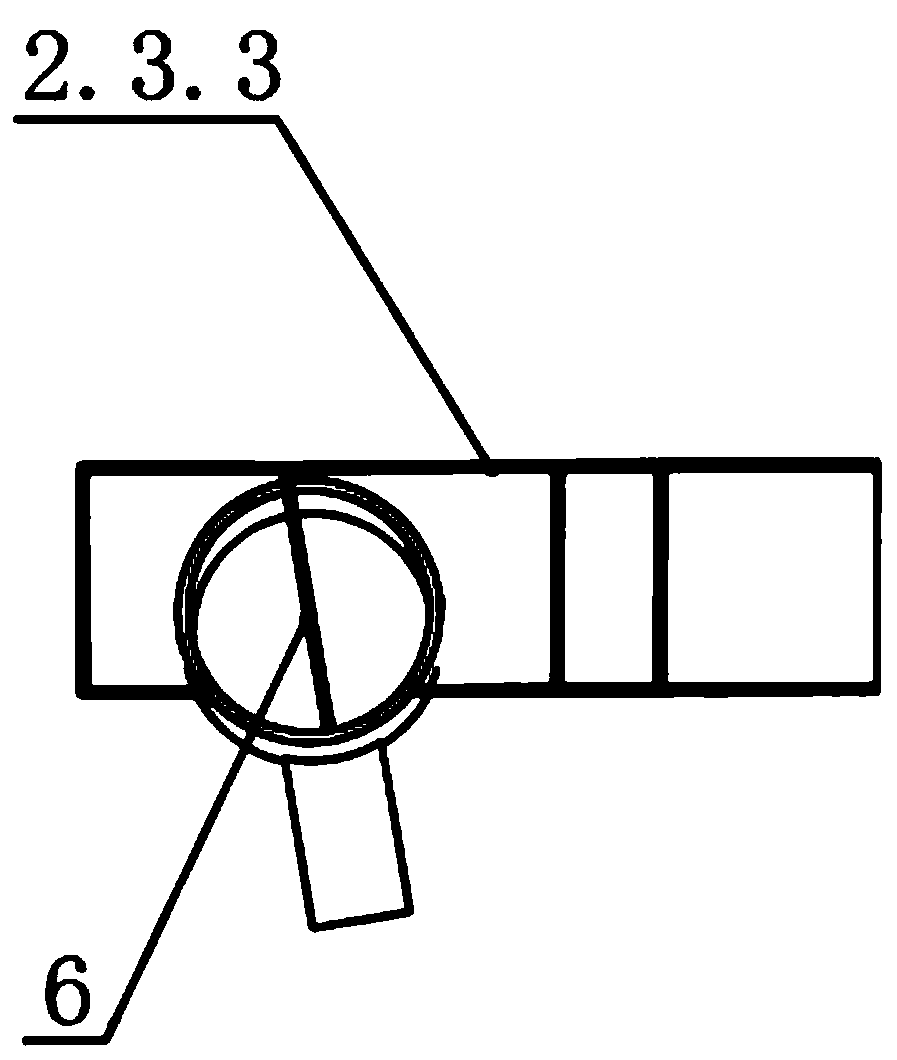
[0042] Step 1: Assemble the box-shaped upper flange plate with the first box-shaped web, the second box-shaped web, the third box-shaped web, the inner partition of the circular tube, and the node circular tube: the box-shaped upper flange plate 2.1 Lay it flat, assemble the first box-shaped web 2.3.1 and the second box-shaped web 2.3.2 on the lower end of one side of the box-shaped upper flange plate 2.1, and assemble the third box-s...


PUM

PropertyMeasurementUnit
thicknessaaaaaaaaaa
thicknessaaaaaaaaaa

Abstract

The invention discloses a manufacturing method for circular-tube penetrating box-type joist steel components. The manufacturing method comprises the steps that a box-type upper flange plate, a first box-type web plate, a second box-type web plate, a third box-type web plate, a circular-tube inner division plate and a joint circular-tube are assembled, and full penetration welding is conducted on an arc-shaped reserved carbon dioxide gas shielded welding gap and a welding groove formed between the box-type upper flange plate and the joint circular-tube; full penetration welding is conducted on a strip-shaped reserved carbon dioxide gas shielded welding gap and a welding groove correspondingly formed between the first box-type web plate and an box-type inner division plate as well as between the first box-type web plate and a box-type left side blanking plate; H-shaped corbels are assembled; a box-type lower flange plate and the joint circular-tube are assembled; a box-type right side blanking plate is assembled; the three H-shaped corbels are assembled to the outer wall of a circular tube; the circular tube is in butt joint with the joint circular-tube; and welding joints between the H-shaped corbels and the circular tube are welded. The manufacturing method for the circular-tube penetrating box-type joist steel components has the advantages of reducing welding stress and deformation. The invention further discloses a steel component structure which adopts the manufacturing method for the circular-tube penetrating box-type joist steel components.

Description

technical field [0001] The invention relates to the technical field of building steel structure processing and manufacturing, more specifically, it relates to a manufacturing method of a box girder steel member through which a circular tube penetrates. The present invention also relates to a steel component structure adopting the manufacturing method of the circular tube penetrating box girder steel component. Background technique [0002] The component forms of steel structures mainly include four basic forms: cross, H-shaped, box-shaped, and round tubes; today's architectural steel structure shapes are diversified, resulting in increasingly diverse building structures. Diversification of structures will inevitably lead to diversity of components. Therefore, in order to achieve a variety of structural shapes, it is necessary to combine the basic forms of various components; a round tube through-beam steel component that combines round tubes and box-type Unique advantages, ...

Claims


Application Information

Patent Timeline
Patent Type & Authority Patents(China)
IPC IPC(8): B23K9/00B23K9/173B23K9/235
Inventor 程登张发荣姜殿忠王笛金欣夏远炎杨杰
Owner 湖北精工工业建筑系统有限公司
Why Eureka
Try Eureka