
Method and device for controlling cooling speed of core assembly casting

A technology of cooling speed and control method, which is applied in the direction of casting molding equipment, casting molds, mold cores, etc., can solve the problems of poor thermal conductivity of sand molds, difficult control, and difficulty in ensuring the internal compactness of local thick and large castings, so as to ensure the internal quality Effect

Inactive Publication Date: 2013-03-13
SUZHOU MINGZHI TECH
View PDF4 Cites 6 Cited by
  • Summary
  • Abstract
  • Description
  • Claims
  • Application Information

AI Technical Summary

Problems solved by technology

However, the disadvantages of core casting compared with metal mold casting or green sand are that the cooling rate of castings is slow and not easy to control, it is difficult to achieve sequential solidification or local rapid cooling, and it is difficult to ensure the intrinsic compactness of locally thick castings
In some cases, the ideal result cannot be achieved even with the troublesome cold iron
This shortcoming makes the core casting process have certain limitations on castings with high quality requirements, complex shapes and local hot spots, such as aluminum alloy cylinder head castings in the automotive industry
[0003] At present, the core casting adopts the natural cooling method to realize the solidification of molten metal in the sand mold. Heat generation makes the cooling speed of castings slow, and it is not easy to control, it is difficult to achieve sequential solidification or local rapid cooling, and it is difficult to ensure the internal compactness of locally thick and large castings. result

Method used


Image

  • Method and device for controlling cooling speed of core assembly casting
  • Method and device for controlling cooling speed of core assembly casting
  • Method and device for controlling cooling speed of core assembly casting

Examples


Embodiment Construction

[0023] Below in conjunction with accompanying drawing and embodiment example, the present invention will be further described:

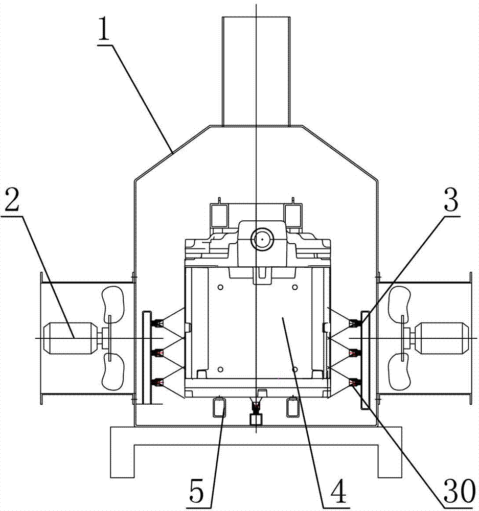
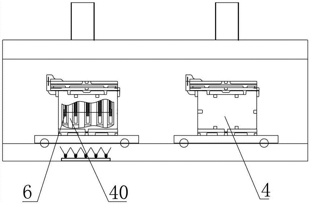
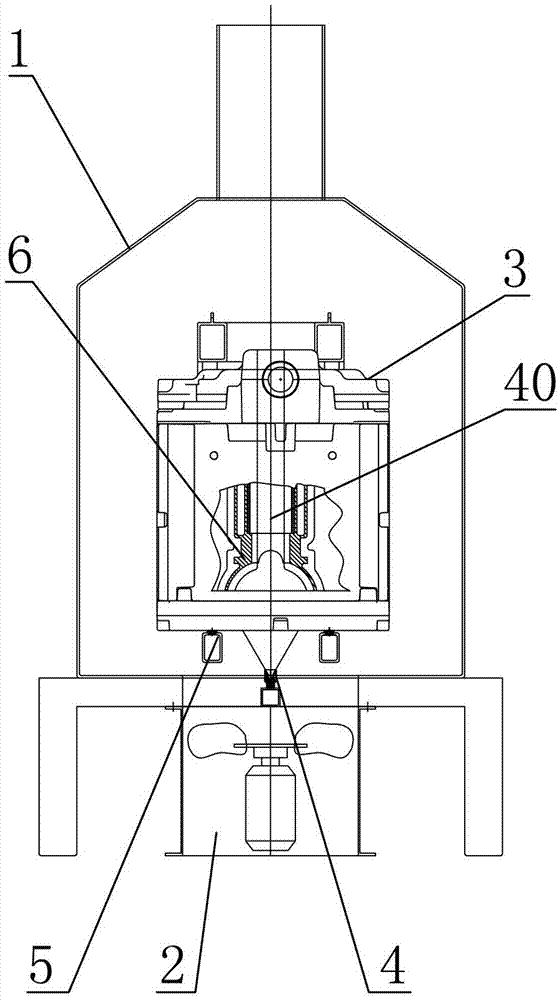
[0024] A method for controlling the cooling speed of core group casting. The molten metal is poured into the sand mold, and the airflow or water mist is sprayed on the part of the sand mold corresponding to the local thick hot spot of the casting, so as to accelerate the cooling and solidification of the casting inside the sand mold, and achieve local The effect of rapid cooling can avoid the casting pine defects caused by hot spots, and the cooling speed can be controlled by adjusting the air flow and water mist volume, among which: the air pressure of the air flow is 320~1500Pa, and the air flow volume is 10000~20000m 3 / h; the spray pressure of water mist is 5~7bar, and the spray volume of water mist is 10~30kg / min.

[0025] Such as figure 2 As shown: the sand mold 4 is provided with a cooling channel 40 at the part corresponding to th...


PUM


Abstract

The invention relates to a method for controlling the cooling speed of core assembly casting, which is characterized in that molten metal is poured in a sand mold, and airflow or water mist is sprayed onto a part of the sand mold, which is corresponding to the local thick part of a cast, so that cooling and solidification of the cast inside the sand mold can be accelerated. An airflow or water mist spraying device for controlling the cooling speed of core assembly casting comprises a framework, an airflow or water mist generating device and a spraying device; the airflow or water mist generating device is communicated with the spraying device; and the spraying device can spray the sand mold placed in the framework. According to the invention, an external physical cooling measure, namely airflow or water mist spraying, and the device are used for controlling the cooling speeds of different positions of core assembly casting, so as to realize rapid cooling or local rapid cooling and ensure the inner quality of the cast; and therefore, the core assembly casting process can be used for mass production of casts with high quality requirements, complicated shapes and local thermal centers, such as aluminium alloy cylinder bodies and cylinder covers in the industry of automobiles.

Description

technical field [0001] The invention relates to a casting core assembly process, in particular to a method and device for controlling the cooling rate of core assembly casting. Background technique [0002] The core casting process has the advantages of accurate casting size, good surface quality, and easy recycling of single sand, and is being widely used. However, the disadvantages of core casting compared with metal mold casting or green sand are that the cooling rate of castings is slow and not easy to control, it is difficult to achieve sequential solidification or local rapid cooling, and it is difficult to ensure the inherent compactness of locally thick castings. In some cases, the ideal result cannot be achieved even with the more troublesome cold iron. This shortcoming makes the core casting process have certain limitations on castings with high quality requirements, complex shapes and local hot spots, such as aluminum alloy cylinder head castings in the automotiv...

Claims


Application Information

Patent Timeline
Patent Type & Authority Applications(China)
IPC IPC(8): B22D27/04B22C9/10
Inventor 吴勤芳吴伟强
Owner SUZHOU MINGZHI TECH
Learn More