Installation method of ring welding backing plate

A ring-shaped welding and installation method technology, applied in welding equipment, auxiliary welding equipment, welding/cutting auxiliary equipment, etc., can solve the problems of many process steps, unfavorable production efficiency and product quality, long side beam manufacturing process, etc., to achieve Guarantee the effect of assembly clearance

Active Publication Date: 2019-05-14
CRRC NANJING PUZHEN CO LTD
View PDF5 Cites 0 Cited by
  • Summary
  • Abstract
  • Description
  • Claims
  • Application Information

AI Technical Summary

Problems solved by technology

The side beam manufacturing process of this process is long, involves many process steps, and requires cross-regional operations; at the same time, the use of this process requires precise control of the size of the beam tube and side beam assembly to ensure the assembly gap between the beam tube and the side beam web, and to ensure that the weld The quality of fusion at the root of the seam is unfavorable for improving production efficiency and product quality

Method used


Image

  • Installation method of ring welding backing plate
  • Installation method of ring welding backing plate
  • Installation method of ring welding backing plate

Examples


Embodiment Construction

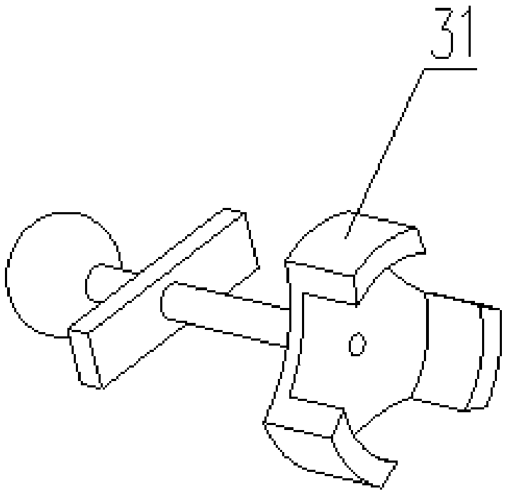
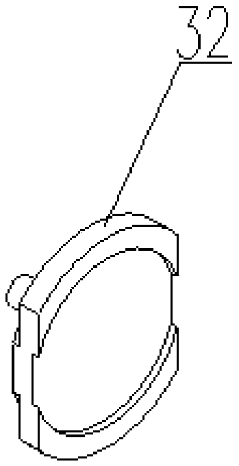
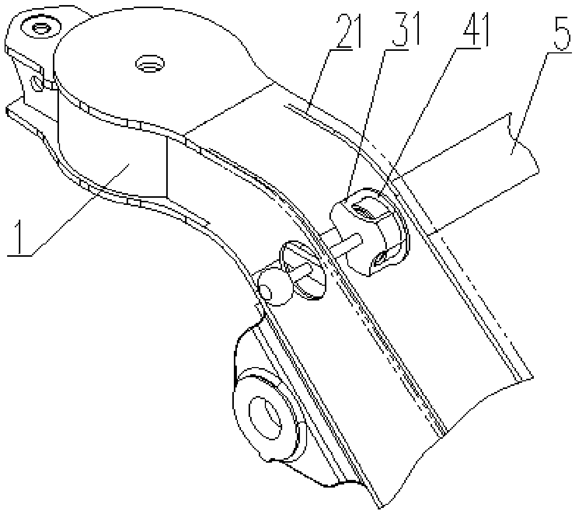
[0021] The installation method of the annular welding backing plate in this embodiment is realized by means of special tooling. The special frock has a first device 31 (see figure 1 ) and the second device 32 (see figure 2 ), the first device 31 has a head for clamping the end of the tubular beam and a tightening device that pushes the head forward. The tightening device includes a screw rod and a support piece, and the support piece is screwed on the screw rod Above, the front end of the screw rod is connected with the head, and the rear end of the screw rod is fixed with a ball head. The front side of the second device 32 has a draw-in slot for the insertion of the end of the tubular beam, and the back side has a step for accommodating an annular welding backing plate, and the back step is fixed with an outwardly protruding handle.

[0022] When the end of the tubular beam is inserted into the slot, the annular welding backing plate is placed on the step, and the axis of ...


PUM


Abstract

The invention relates to an installation method for an annular welding base plate. The installation method is achieved through a special tool, it can be ensured that the annular welding base plate is positioned and fixed when the annular welding base plate and a pipe type cross beam are in a concentric state, and welding and assembling operation of the annular welding base plate is completed. By means of the installation method, the problem that a traditional pipe type cross beam and box type side beam assembling process is low in efficiency is solved, assembling of the pipe type cross beam and the box type side beam can be rapidly achieved, and an assembling gap of an annular weld seam is guaranteed. By matching the device positioning hole diameter, the installation method can be widely applied to production of assembling structures of pipe type cross beams with different pipe diameters and box type side beams.

Description

technical field [0001] The invention relates to a method for installing an annular welding backing plate, belonging to the technical field of rail vehicle bogies. Background technique [0002] In the traditional bogie frame structure, the assembly process of tubular beams and box-shaped side beams is usually formed by welding the side beams and then machining through holes at the webs of the side beams to be paired with the tubular beams. The side beam manufacturing process of this process is long, involves many process steps, and requires cross-regional operations; at the same time, the use of this process requires precise control of the size of the beam tube and side beam assembly to ensure the assembly gap between the beam tube and the side beam web, and to ensure that the weld The quality of fusion at the root of the seam is unfavorable for improving production efficiency and product quality. [0003] In order to reduce the technological process, reduce the influence of...

Claims


Application Information

Patent Timeline
Patent Type & Authority Patents(China)
IPC IPC(8): B23K37/04
CPCB23K37/04B23K2101/006
Inventor 方孝钟倪宝成刘海兵孙佳杨宝林宋玉奇张迪
Owner CRRC NANJING PUZHEN CO LTD
Why Eureka
Try Eureka