
an injection mold

An injection mold and movable mold technology, which is applied in the field of injection molding tools for plastic products, can solve the problems of weak sliding stability of the side core slider, affecting the service life of the side core pulling mechanism, etc., so as to improve the sliding stability, The effect of improving the service life

Active Publication Date: 2019-07-26
台州市三鼎模塑有限公司
View PDF2 Cites 0 Cited by
  • Summary
  • Abstract
  • Description
  • Claims
  • Application Information

AI Technical Summary

Problems solved by technology

[0003] To realize the sliding action of the side core slider, a sliding groove is usually provided on the surface of the corresponding movable mold, and the side core is slidably connected in the sliding groove. Since the height of the entire side core block is high, if only relying on The sliding groove limit slip effect, the sliding stability of the entire side core slider is not strong, which will affect the actual service life of the entire side core pulling mechanism

Method used


Image

  • an injection mold
  • an injection mold
  • an injection mold

Examples


Embodiment 1

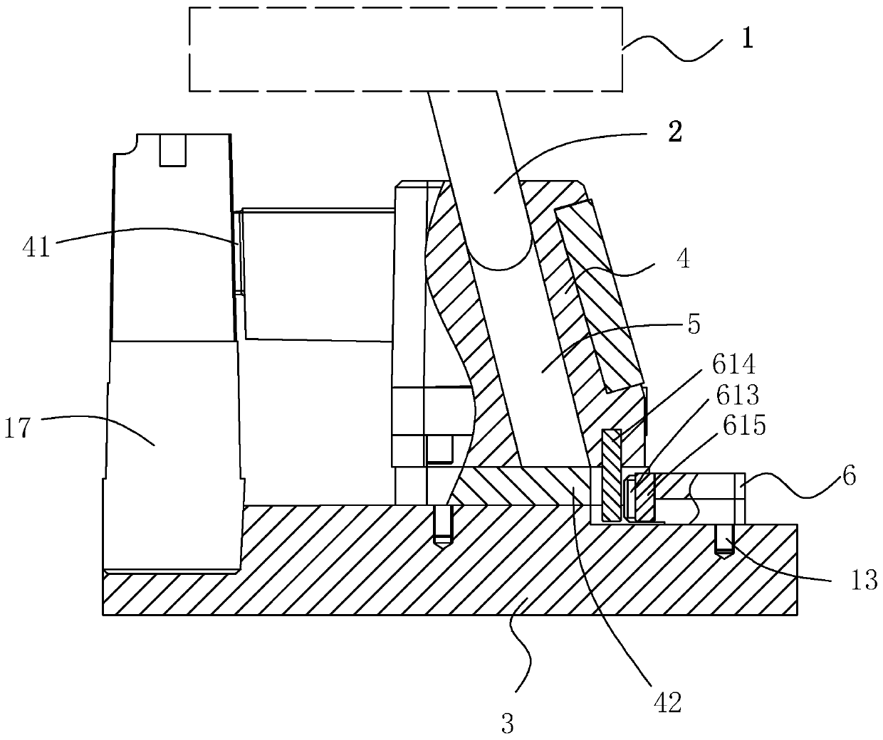
[0034] A side-drawing limit mechanism, see figure 1 , including the first installation platform 1 and the second installation platform 3, the first installation platform 1 and the second installation platform 3 can be separated or approached each other, the first installation platform 1 is connected with a slanted guide column 2, and the second installation platform The side core slide block 4 is connected with sliding on the side of mounting platform 3, and side core sliding block 4 is provided with oblique guide hole 5, is used for forming the molding end 41 of plastic product 17 mounting holes; When the first mounting platform 1 When approaching or moving away from the second installation table 3 , the inclined guide post 2 is inserted into the inclined guide hole 5 to drive the entire side core slider 4 to slide back and forth along the second installation table 3 .

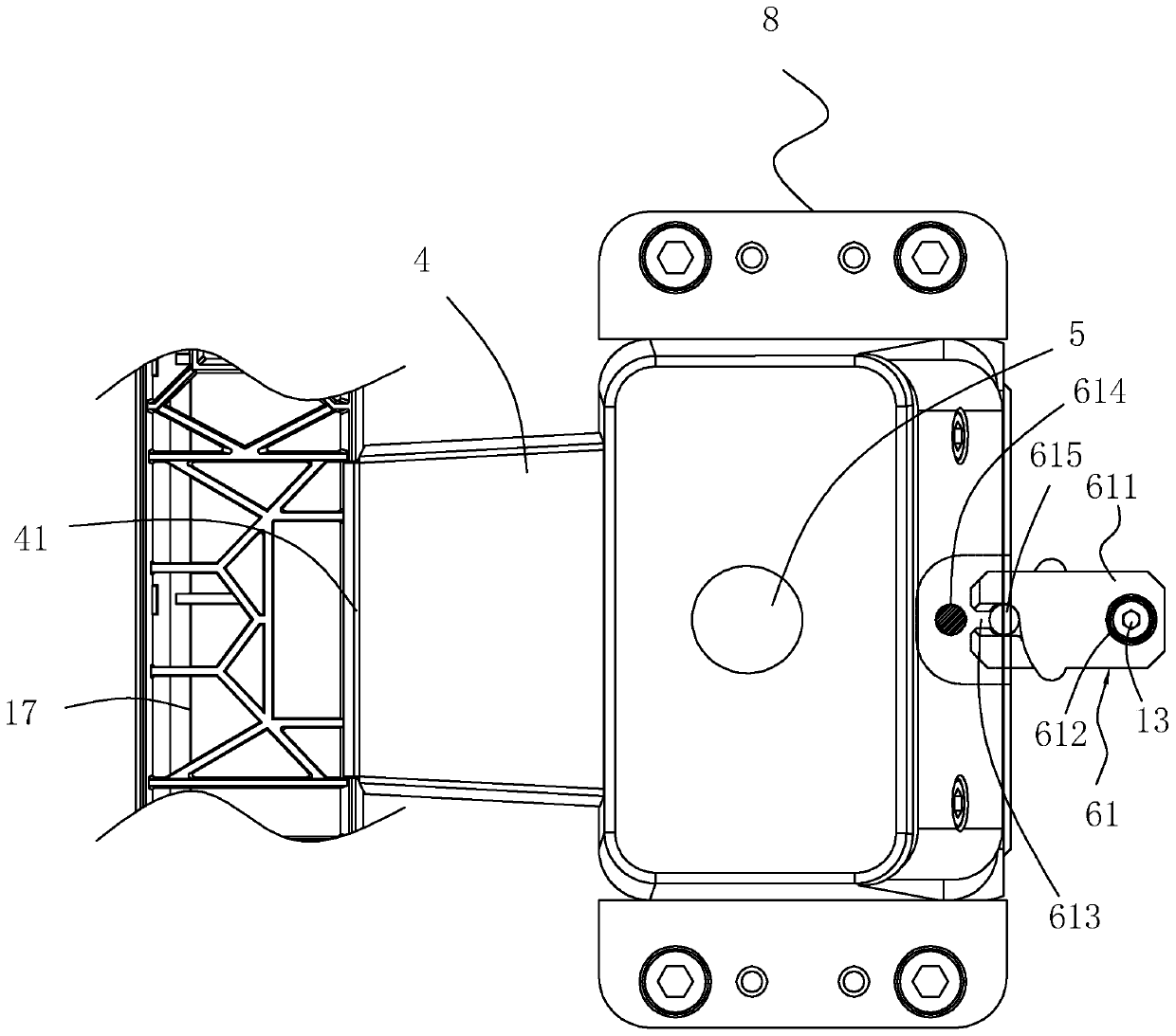
[0035] see figure 1 as well as figure 2 , on the side of the side core slide block 4 away from the formin...

Embodiment 2

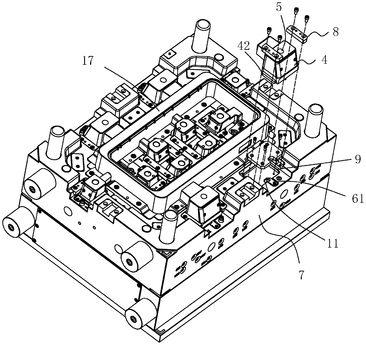
[0041] An injection mold, see figure 1 as well as image 3 , including a movable mold 7, a fixed mold, and a side-drawing limit mechanism as in Embodiment 1. The second mounting table 3 in Embodiment 1 is a movable mold 7, and the first mounting table 1 is a fixed mold, and the side-drawing limit mechanism Mechanism is installed on the moving mold 7.

[0042] Specifically, see image 3 as well as Figure 5 , the parting surface of the movable mold 7 is provided with a first installation groove 9, a pressure plate 8 is installed on the groove wall of the second installation groove 11, and a chute 10 is formed between the pressure plate 8 and the groove bottom of the first installation groove 9, and the side profile The core slider 4 is provided with a sliding block 42. When the side core slider 4 is located in the first installation groove 9, the sliding block 42 cooperates with the chute 10, and the entire side core slider 4 can move along the first installation groove 9. ...


PUM


Abstract

The invention discloses an injection mold and a side pulling limiting mechanism thereof. According to the technical scheme, the injection mold is characterized by comprising a first installing table, an inclined guiding column connected to the first installing table, a second installing table and a side mold core slider; the side mold core slider is provided with an inclined guiding hole and a forming end; the first installing table and the second installing table can be separated from or get close to each other; the inclined guiding column and the inclined guiding hole are matched in an inserted connection manner so as to drive the side mold core slider to slide back and forth; a main limiting part is further included, and comprises a limiting clamp assembly installed on the second installing table; the limiting clamp assembly comprises at least two limiting clamp pieces and a torsion spring; a clamp gap exists between every two adjacent limiting clamp pieces; the side mold core slider is provided with a limiting block; the side pulling limiting mechanism is arranged in the mold; the power of an auxiliary limiting assembly comes from the action generated by the limiting clamp pieces; the limiting end in the auxiliary limiting assembly can abut against a sliding block, and the limiting end and the sliding block are mutually matched, the sliding stability of the side mold core slider is substantially improved, and the overall service life of the mold is prolonged.

Description

technical field [0001] The invention relates to an injection molding tool for plastic products, in particular to an injection mold. Background technique [0002] Existing injection molding molds for plastic products, such as the Chinese invention patent CN105150468A with the notification number CN105150468A, have side-pulling injection molds, which mainly include a fixed mold and a moving mold inside. For the molding cavity of the product, for some plastic products with mounting holes on the outer wall, a side core-pulling mechanism will be installed at the corresponding mounting hole. The side core-pulling mechanism can refer to the attached figure 1 , the side core-pulling mechanism includes a side core slider, the end of the side core slider is used to form a mounting hole, and an oblique guide hole is also set in the side core slider, and an oblique guide post is also provided, and the oblique guide post is inserted into the into the inclined guide hole, and can be used...

Claims


Application Information

Patent Timeline
Patent Type & Authority Patents(China)
IPC IPC(8): B29C45/33B29C45/40
CPCB29C45/33B29C45/332B29C45/4005
Inventor 王统良
Owner 台州市三鼎模塑有限公司
Learn More