
Collar of retractable arches and retractable arches

A shrinkable arch technology, which is applied in the field of card and retractable arch, can solve the problems of weak strength at the lap joint, slip resistance of the retractable arch, and large bending of the card, so as to improve the strength and rigidity , Sliding stability is improved, and the effect of optimizing the force condition

Active Publication Date: 2022-05-10
CHINA RAILWAY HI TECH IND CORP LTD +1
View PDF7 Cites 0 Cited by
  • Summary
  • Abstract
  • Description
  • Claims
  • Application Information

AI Technical Summary

Problems solved by technology

[0003] In the existing shrinkable arch structure, it has always been a common problem that the strength of the lap joint of two sections of section steel is weak. The lap joint of two sections of section steel is connected by a card. Increasing, under the action of external force, the overlapping part of the two sections of steel will produce relative slip and contraction, so that the connecting bolts of the card will be subjected to the shear force of the slip, and the card will be greatly bent and the bolts will be bent. When the relative sliding distance exceeds the specified value, the card will be destroyed, which will lead to a significant reduction in the strength of the entire retractable arch, which may cause serious safety problems
Moreover, when the section steel shrinks and slides under the action of external force, the two sections of section steel will also bite each other at the erection, which will cause the shrinkable arch to resist slipping, making it a rigid arch and losing its flexibility. Significance of shrinkage arch itself

Method used


Image

  • Collar of retractable arches and retractable arches
  • Collar of retractable arches and retractable arches
  • Collar of retractable arches and retractable arches

Examples


Embodiment Construction

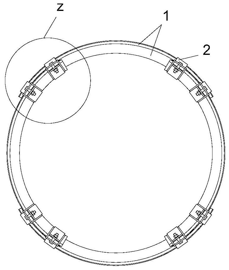
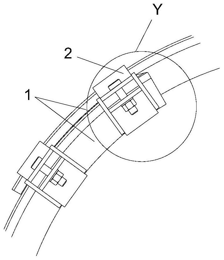
[0022] Such as Figure 1 to Figure 4 The shrinkable arch frame of the present invention as shown includes several sections of U-shaped steel 1 overlapping up and down, and the two sections of U-shaped steel 1 are clamped and fitted by clamps 2 at the overlapping section of the two sections of U-shaped steel 1 .

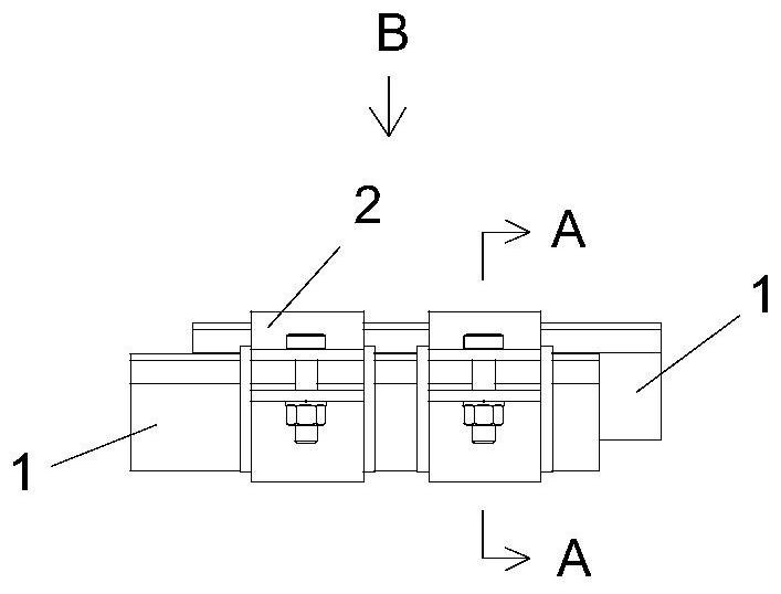
[0023] Such as Figure 3 to Figure 6 As shown, the clamp 2 has an upper clamping plate 21 and a lower clamping plate 25 which are detachably connected. The clamping width of the upper clamping plate 21 is adapted to the upper opening width of the U-shaped steel 1 in the retractable arch, and the clamping width of the lower clamping plate 25 is adapted to the section width of the U-shaped steel 1 in the retractable arch. The lower end of the side of the upper clamping plate 21 is provided with upper clamping plate ears extending to both sides, and the upper end of the side of the lower clamping plate 25 is also provided with lower clamping plate ears extending to both...


PUM


Abstract

The invention relates to a collapsible arch frame and a collapsible arch frame, wherein the collapsible arch frame has an upper clamp plate and a lower clamp plate that are detachably connected, and the clamping width of the upper clamp plate is the same as that of the medium-shaped steel of the retractable arch frame. The width of the upper opening is adapted, and the clamping width of the lower clamping plate is adapted to the section width of the medium-shaped steel of the retractable arch frame. The upper end of the side of the lower clamping plate is provided with lower clamping plate ears extending to both sides. Ribs are provided between the upper part and the side of the lower clamping plate; a protruding structure is provided at the upper end of the side of the lower clamping plate for fitting with the fillets of the ears of the section steel. The invention effectively improves the strength and rigidity of the frame, obviously optimizes the structure of the frame and the force condition of the frame, and at the same time greatly improves the sliding stability of the retractable arch joint, and avoids the The occlusal phenomenon occurs during the sliding process of the section steel, thereby avoiding the phenomenon of anti-slipping of the shrinkable arch.

Description

technical field [0001] The invention relates to equipment for building construction, in particular to a retractable arch frame and a retractable arch frame. Background technique [0002] Shrinkable arches are also called flexible arches, which are mainly suitable for the initial support after tunnel excavation, for example, in order to limit the excessive displacement of the surrounding rock and maintain the stability of the surrounding rock and provide the minimum loosening pressure greater than the damage of the surrounding rock. support resistance. Its shape is not limited to round, but also has door arch, horseshoe and other shapes. The surrounding rock of the tunnel shrinks and deforms under the action of the ground stress, and the shrinkable arch shrinks along with the surrounding rock, so that the self-supporting capacity of the surrounding rock can be fully exerted, the pressure of the surrounding rock can be reduced, and a certain amount of deformation of the surro...

Claims


Application Information

Patent Timeline
Patent Type & Authority Patents(China)
IPC IPC(8): E21D11/22
CPCE21D11/22
Inventor 张浩文李恒高旭东梅元元周鸿雏王钰辰郑军罗红梅
Owner CHINA RAILWAY HI TECH IND CORP LTD
Learn More