High-efficiency garbage compression device

A garbage compression and high-efficiency technology, applied in the direction of presses, irradiation, manufacturing tools, etc., can solve the problems of incomplete solid-liquid separation, low compression efficiency, bacteria discharge, etc., achieve long compression time, high compression efficiency, and ensure hygiene Effect

Inactive Publication Date: 2017-12-15
曹欢
0 Cites 7 Cited by

AI-Extracted Technical Summary

Problems solved by technology

[0003] At present, some domestic waste, especially non-recyclable waste, usually needs to be processed after compression. However, some existing waste compression devices have low compression efficienc...

Abstract

The invention discloses a high-efficiency garbage compression device, which comprises a shell, and the bottom of the shell is provided with a lower supporting frame, the lower supporting frame is a T-shaped bracket, and rollers are respectively fixed on both ends of the top of the lower supporting frame, and the lower supporting frame is The two ends of the support frame are respectively provided with rollers, the rollers are set on the rollers, and the drive motor connected to the rollers is arranged on the outer side of the housing corresponding to the rollers; the lower conveyor belt is set between the two rollers, and the An upper supporting frame is arranged above the lower conveyor belt, the upper supporting frame is an inverted T-shaped bracket, and a fixed frame is arranged above the upper supporting frame; vertical guide rails are fixedly arranged at the bottom of the fixed frame. The garbage compression device has a novel structure; the invention ingeniously sets the compression mechanism to compress during the transmission process, and the compression efficiency is high; and the compression time is long, the garbage is hard to rebound after being compressed and shaped, and the solid and liquid are separated after compression; at the same time, sterilization is carried out during the compression process to ensure hygiene .

Application Domain

PressesRadiation

Technology Topic

Drive motorEngineering +3

Image

  • High-efficiency garbage compression device
  • High-efficiency garbage compression device
  • High-efficiency garbage compression device

Examples

  • Experimental program(1)

Example Embodiment

[0019] The technical solutions in the embodiments of the present invention will be clearly and completely described below in conjunction with the accompanying drawings in the embodiments of the present invention. Obviously, the described embodiments are only a part of the embodiments of the present invention, rather than all the embodiments. Based on the embodiments of the present invention, all other embodiments obtained by those of ordinary skill in the art without creative work shall fall within the protection scope of the present invention.
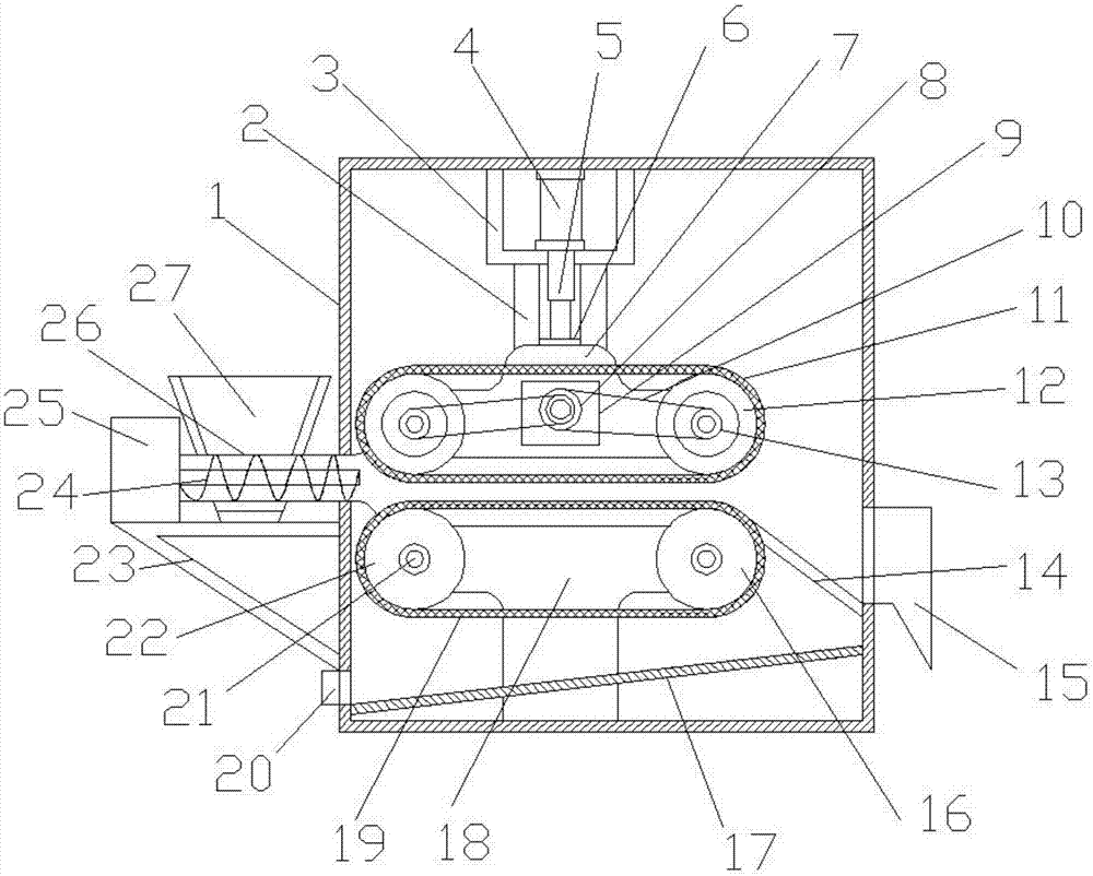
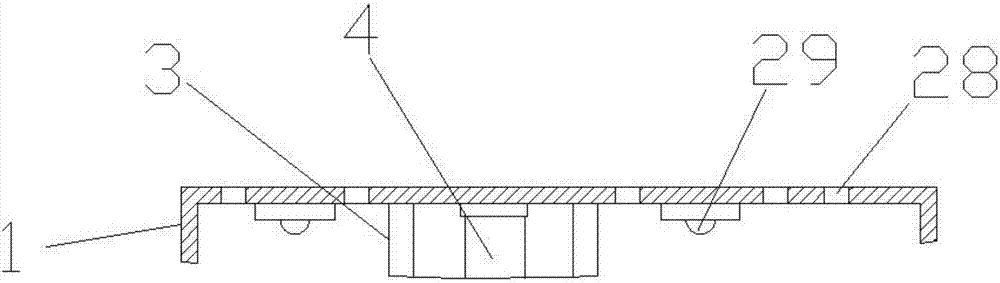
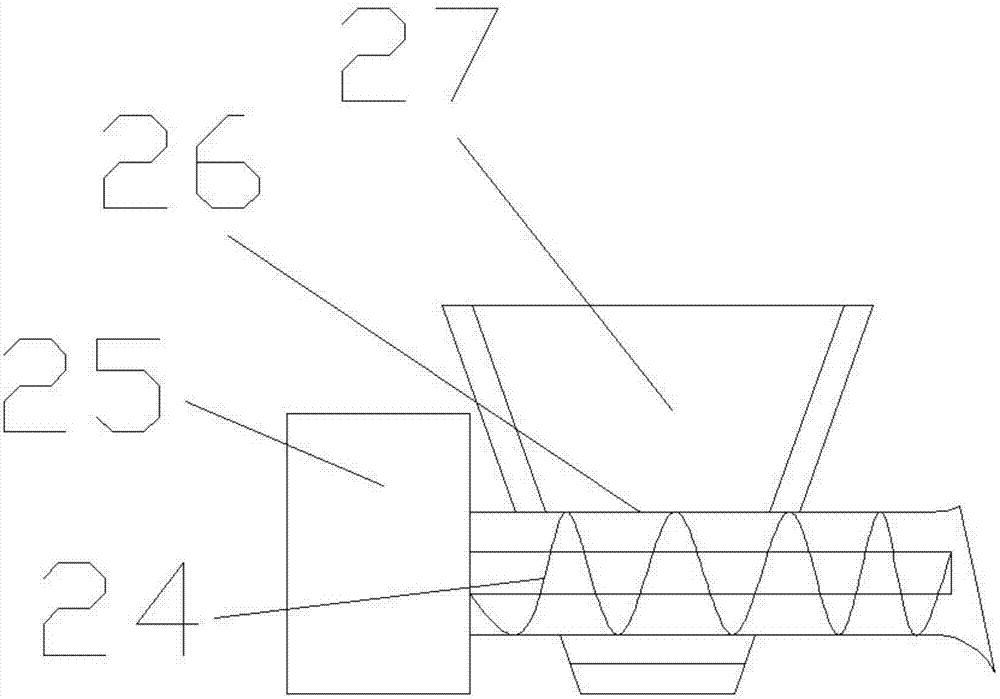
[0020] See Figure 1~4 In an embodiment of the present invention, a high-efficiency garbage compression device includes a housing 1, and a lower support frame 18 is provided at the inner bottom of the housing 1. The lower support frame 18 is a T-shaped support, and the top of the lower support frame 18 is two The two ends of the lower support frame 18 are respectively fixed with rollers 16, the two ends of the lower support frame 18 are respectively provided with rollers 21, the rollers 16 are sleeved on the roller 21, and the outer side of the housing 1 is provided with the roller 21 on the side corresponding to the roller 21. A drive motor connected by transmission; a lower conveyor belt 19 is sleeved between the two rollers 16 and the lower conveyor belt 19 is a mesh-shaped conveyor belt; an upper support frame 7 is arranged above the lower conveyor belt 19, and the upper support frame 7 is an inverted T The upper support frame 7 is provided with a fixed frame 3, the bottom end of the fixed frame 3 is fixedly provided with a vertical guide rail 2, the vertical guide rail 2 is sleeved with a slider 6, and the upper support frame 7 The top end is fixed on the lower side of the slider 6, a cylinder 4 is installed on the fixing frame 3, a piston rod 5 is arranged on the cylinder 4, and the bottom end of the piston rod 5 is fixedly connected to the slider 6; the upper support frame 7 The left and right ends are respectively sleeved with crawler wheels 12, the crawler wheels 12 are sleeved on the rollers 21 respectively provided at both ends of the upper support frame 7, and the crawler 11 is sleeved between the two crawler wheels 12, and the side of the crawler wheel 12 A driven pulley 13 is provided, a driving pulley 8 is provided in the middle of the upper support frame 7, and the driving pulley 8 is driven by a pulley motor 10 provided on the upper support frame 7 through a transmission shaft; the driving pulley 8 Two belt grooves are provided on the upper part, and the driving pulley 8 is respectively connected to the left and right driven pulleys 13 through a belt 9; a feeding mechanism is provided between the corresponding crawler belt 11 and the lower transmission belt 19 on the outer side of the housing 1, so The feeding mechanism includes a feeding barrel 26. The nozzle of the feeding barrel 26 is horn-shaped and is arranged between the left crawler belt 11 and the lower transmission belt 19; a feeding hopper 27 is provided on the left end of the feeding barrel 26 , The feeding barrel 26 penetrates the bottom of the feeding hopper 27, a tripod 23 supporting the feeding hopper 27 is provided on the outer side wall of the housing 1, a screw feeding shaft 24 is provided in the feeding barrel 26, and the outer side of the feeding barrel 26 The end is provided with a feeding motor 25 that drives the screw feeding shaft 26 to rotate. The feeding motor 25 is fixed on a tripod 23 on the outer side of the feeding hopper 27. The right side of the housing 1 corresponds to the lower right end of the lower conveyor belt 19. An inclined guide plate 14 is provided with a discharge port 15 on the right side wall of the housing corresponding to the bottom end of the guide plate 14, and an inclined guide plate 17 is provided at the inner bottom of the housing 1. 1. A liquid outlet 20 is provided at the left bottom end of the corresponding baffle plate 17, and the top of the casing 1 is provided with a plurality of ventilation holes 28 for exhaust; the inner top of the casing 1 is provided with ultraviolet sterilization on the left and right sides 灯29.
[0021] The working principle of the present invention is that the compressible garbage enters the hopper 27, and enters the lower conveyor belt under the rotation of the screw feeding shaft through the feeding barrel at the bottom of the hopper. The cylinder 4 drives the upper support frame along the vertical direction through the piston rod 5. Move downwards to the guide rail, driving the crawler on the upper support frame to compress the garbage on the lower conveyor belt. The garbage is compressed and shaped for a long time between the crawler and the lower conveyor belt and discharged from the discharge port through the guide plate from the right end, and is generated during the compression process The sewage overflows from the sieve holes on the lower conveyor belt, and is discharged from the liquid outlet through the deflector; the gas generated during the compression process is discharged from the top vent hole, and the ultraviolet germicidal lamp in the shell sterilizes the inner cavity of the shell.
[0022] For those skilled in the art, it is obvious that the present invention is not limited to the details of the foregoing exemplary embodiments, and the present invention can be implemented in other specific forms without departing from the spirit or basic characteristics of the present invention. Therefore, from any point of view, the embodiments should be regarded as exemplary and non-limiting. The scope of the present invention is defined by the appended claims rather than the foregoing description, and therefore it is intended to fall within the claims. All changes within the meaning and scope of equivalent elements of are included in the present invention. Any reference signs in the claims should not be regarded as limiting the claims involved.
[0023] In addition, it should be understood that although this specification is described in accordance with the embodiments, not every embodiment only includes an independent technical solution. This narration in the specification is only for clarity, and those skilled in the art should consider the specification as a whole The technical solutions in the embodiments can also be appropriately combined to form other implementations that can be understood by those skilled in the art.

PUM

no PUM

Description & Claims & Application Information

We can also present the details of the Description, Claims and Application information to help users get a comprehensive understanding of the technical details of the patent, such as background art, summary of invention, brief description of drawings, description of embodiments, and other original content. On the other hand, users can also determine the specific scope of protection of the technology through the list of claims; as well as understand the changes in the life cycle of the technology with the presentation of the patent timeline. Login to view more.

Similar technology patents

Efficient sludge drying treatment device

PendingCN107335279Anovel structureImprove dehydration efficiency
Owner:ZHENGZHOU UNIV

Air purifier capable of automatically removing dust

Owner:JIANGSU CHUANGLAN SOLAR AIR CONDITIONER

Diaryl benzo pyridine derivative, and preparation and use thereof

InactiveCN101463014Ahigh selectivity indexnovel structure
Owner:FUDAN UNIV

Bactericide composition containing coumoxystrobin with synergistic effect

InactiveCN104430357Anovel structureunique mode of action
Owner:JILIN BADA PESTICIDE

Classification and recommendation of technical efficacy words

  • improve compression efficiency
  • novel structure

Cyclone compressor possessing lubricating system

ActiveCN101338754Agood lubricationimprove compression efficiency
Owner:DALIAN SANYO COMPRESSOR

Image processing method and device

ActiveCN107087201Aimprove compression efficiencyHigh Image Restoration Quality
Owner:XIAN WANXIANG ELECTRONICS TECH CO LTD

Backpack medlar-picking machine

InactiveCN101473731Aeasy to movenovel structure
Owner:CHINA AGRI UNIV

Power storage device and electronic device

ActiveUS20160372717A1high capacitynovel structure
Owner:SEMICON ENERGY LAB CO LTD
Why Eureka
Try Eureka