Drone with adjustable lights

An unmanned aerial vehicle, an adjustable technology, applied in the field of unmanned aerial vehicle technology and lighting, can solve the problems of lighting and create stage effects, and achieve the effect of improving stage effects

Active Publication Date: 2020-10-09
浙江航匠创新科技有限公司
View PDF7 Cites 3 Cited by
  • Summary
  • Abstract
  • Description
  • Claims
  • Application Information

AI Technical Summary

Problems solved by technology

[0003] Among them, on many occasions, especially large outdoor stages, due to the limitations of various reasons such as venues and weather, ordinary stage lamps that rely on brackets may not be able to meet the needs of the venue for lighting effects, and cannot be placed outside the lighting bracket and where people cannot touch them. Lighting and staging

Method used


Image

  • Drone with adjustable lights
  • Drone with adjustable lights
  • Drone with adjustable lights

Examples


Embodiment 1

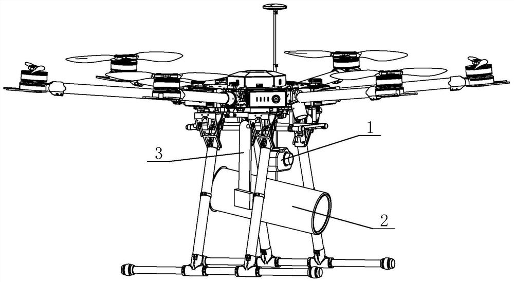
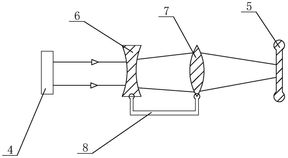
[0032] Such as Figures 1 to 6 The UAV with adjustable lights shown includes a camera 1 and a lamp 2. The camera 1 is installed on the UAV, and the lamp 2 is fixed under the UAV through a bracket 3. There is a device between the lamp 2 and the bracket 3 for adjustment. The angle adjustment structure of the 2 angles of the lamp. The lamp 2 includes a light source 4, a focal length adjustment mechanism for adjusting the focal length according to actual needs, and a combined lens 5 for forming a specific aperture. The focal length adjustment mechanism includes a focusing concave lens 6, a focusing convex lens 7, and a focusing concave , The displacement mechanism 8 of the distance between the convex lenses. Combination lens 5 comprises flat lens and annular convex lens, and described flat lens is circular plane shape, and annular convex lens surrounds the edge of flat lens; Also comprises remote control device and signal receiving circuit, and described remote control device is ...

Embodiment 2

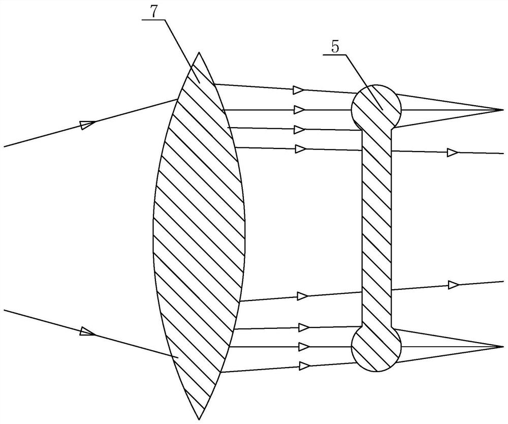
[0042] The difference between this embodiment 2 and embodiment 1 is that the structure of the combination lens 5 has been improved, such as Figure 4 and Figure 5As shown in a, the edge of the flat lens in the combined lens 5 evenly surrounds a circle of spherical lenses. The light irradiated on the edge of the combined lens 5 is focused and refracted by the spherical lens, and forms a circle of continuous and evenly distributed point-like spots around the central aperture produced by the flat lens on the irradiated surface. Such as Figure 6 As shown in a, there is a non-light ring-shaped dark area without light irradiation between the central aperture and the ring-shaped spot

[0043] Among them, in order to facilitate identification and understanding, Figure 6 In the actual lighting imaging effect, the shadow part shown in is a bright light area, while the part without shadow is a dark area without light exposure.

[0044] The lighting effect produced by this embodime...


PUM


Abstract

The invention discloses an unmanned aerial vehicle with adjustable light. The unmanned aerial vehicle comprises a camera and a lamp. The camera is installed on the unmanned aerial vehicle. The lamp is fixed on the lower portion of the unmanned aerial vehicle through a bracket. An angle adjusting mechanism used for adjusting lamp angles is arranged between the lamp and the bracket. The lamp comprises a light source, a focal length adjusting mechanism used for adjusting the focal length according to the actual demands and a combination lens used for forming specific light rings. The combination lens comprises a plate lens and an annular convex lens. According to the unmanned aerial vehicle with adjustable light, the lamp can produce a special lighting effect, meanwhile, operators can control the lighting angles and the focal length of the lamp on the unmanned aerial vehicle through a remote control device, better observation is achieved through the camera, and the light effect is controlled.

Description

technical field [0001] The invention relates to the field of unmanned aerial vehicle technology and lighting, in particular to an unmanned aerial vehicle with adjustable lighting. Background technique [0002] With the development and needs of society, more and more jobs are beyond the reach of human beings, or are more difficult to complete, so unmanned aerial vehicles were born. UAVs are now divided into two types: military and civilian. In terms of civil use, it is used in many fields, such as agriculture, plant protection, micro selfie, express transportation, mapping and many other fields. [0003] Among them, on many occasions, especially large outdoor stages, due to the limitations of various reasons such as venues and weather, ordinary stage lamps that rely on brackets may not be able to meet the needs of the venue for lighting effects, and cannot be placed outside the lighting bracket and where people cannot touch them. For lighting and stage effects. In particul...

Claims


Application Information

Patent Timeline
Patent Type & Authority Patents(China)
IPC IPC(8): G03B17/55B64D47/02B64D47/08
CPCB64D47/02B64D47/08
Inventor 季航
Owner 浙江航匠创新科技有限公司
Why Eureka
Try Eureka