Turbine engine exhaust and noise reduction structure and turbine engine unit
A turbine engine and unit technology, which is applied to engine components, engine functions, machines/engines, etc., can solve the problems of high exhaust speed, high power density, and high noise of turbine engines, and meet the requirements of high-velocity exhaust noise reduction. , speed reduction, noise reduction effect
- Summary
- Abstract
- Description
- Claims
- Application Information
AI Technical Summary
Problems solved by technology
Method used
Image

Examples
no. 1 example
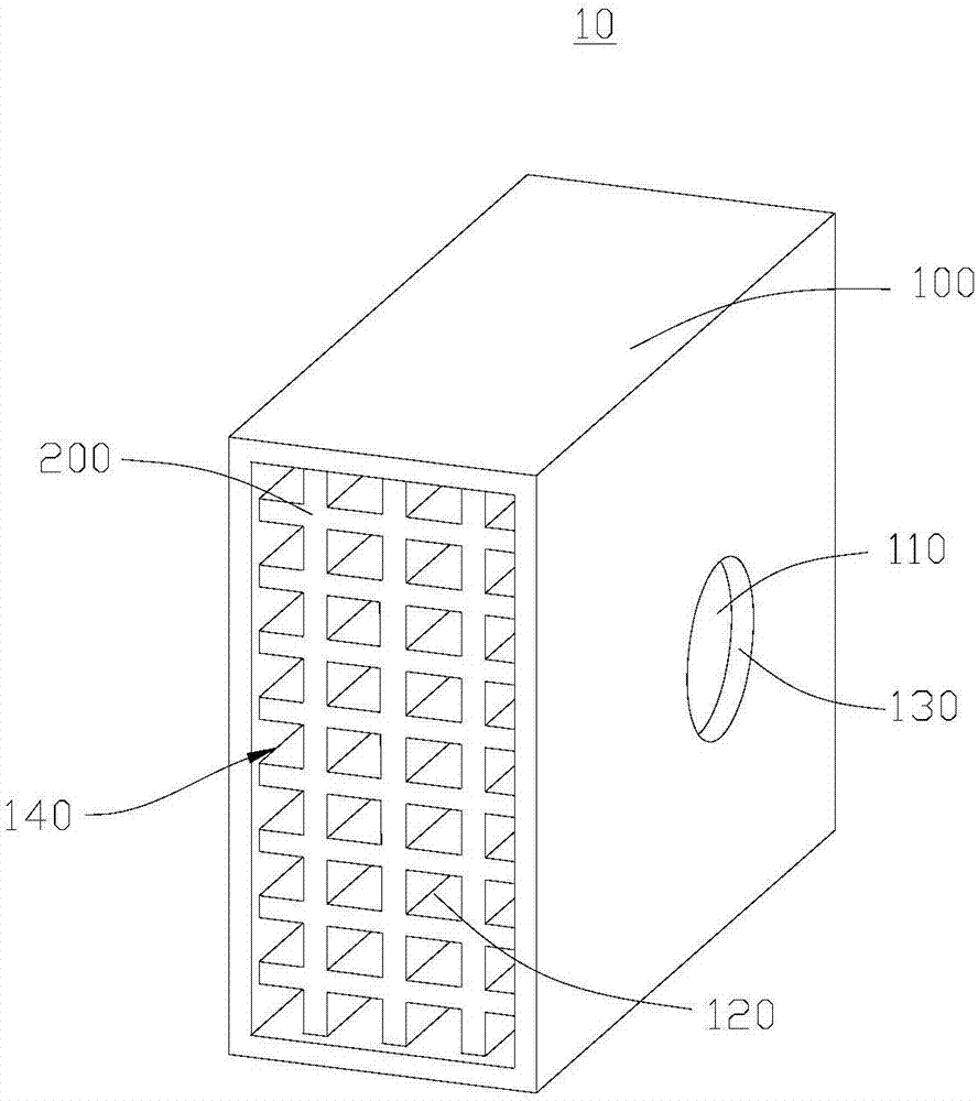
[0032] see figure 1 , a turbine engine exhaust noise reduction structure 10 is provided in this embodiment, which is applied to a turbine engine (not shown in the figure), where the exhaust velocity of the turbine engine is relatively high, and the exhaust noise caused is also particularly large. The turbine engine exhaust noise reduction structure 10 is connected to the turbine engine, which can greatly reduce the exhaust velocity of the turbine engine, and can greatly reduce the regenerative noise generated by the exhaust gas, and can meet the high flow rate noise reduction requirements of the turbine engine.
[0033] Wherein, the turbine engine is provided with an exhaust port (not shown), the turbine engine exhausts through the exhaust port, the turbine engine exhaust noise reduction structure 10 is used to be connected to the exhaust port, and the turbine engine exhaust noise reduction structure 10 It is used to reduce the speed of the exhaust gas discharged from the exha...
no. 2 example
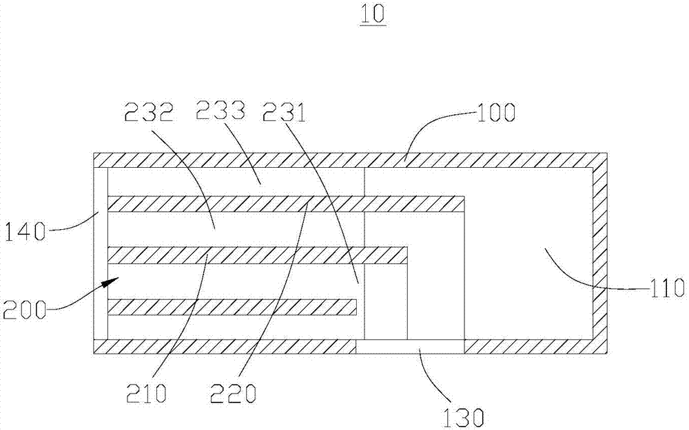
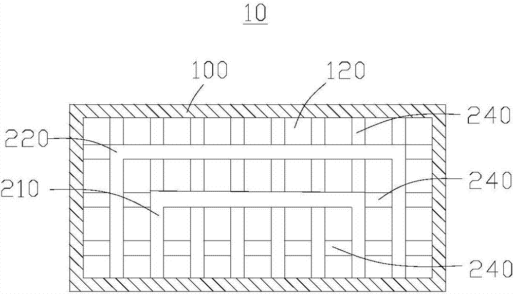
[0052]This embodiment provides a turbine engine unit (not shown), which includes a turbine engine (not shown) and the turbine engine exhaust noise reduction structure 10 provided in the first embodiment. An exhaust port (not shown) is arranged on the turbine engine, and the exhaust port is connected with the air inlet 130, so that the exhaust gas discharged through the exhaust port can enter into the diffusion cavity 110 through the air inlet 130, and After sufficiently diffusing in the diffusion cavity 110 , it is guided to the gas outlet 140 through the guide channel 120 , and is led out through the gas outlet 140 . Wherein, the exhaust noise reduction structure 10 of the turbine engine can reduce the exhaust speed and reduce the noise of the turbine engine unit.
PUM
 Abstract
Description
Claims
Application Information
 - Generate Ideas
- Intellectual Property
- Life Sciences
- Materials
- Tech Scout
- Unparalleled Data Quality
- Higher Quality Content
- 60% Fewer Hallucinations
Browse by: Latest US Patents, China's latest patents, Technical Efficacy Thesaurus, Application Domain, Technology Topic, Popular Technical Reports.
© 2025 PatSnap. All rights reserved.Legal|Privacy policy|Modern Slavery Act Transparency Statement|Sitemap|About US| Contact US: help@patsnap.com