
A vibration damping device and vibration damping method for ship shafting

A vibration damping device and shafting technology, which is applied to the transmission device, shock absorber, liquid shock absorber, etc. of synchronous propulsion components, can solve the problems of occupying limited space in the engine room, consuming vibration energy, and having no vibration damping effect. , to achieve the effects of easy replacement of parts, wide frequency band of vibration reduction, and good adaptability

Active Publication Date: 2019-06-21
JIANGSU UNIV OF SCI & TECH
View PDF9 Cites 0 Cited by
  • Summary
  • Abstract
  • Description
  • Claims
  • Application Information

AI Technical Summary

Problems solved by technology

However, the device must vibrate at a medium to high frequency, so that the positive pressure on the contact surface of the wire mesh reaches a certain amount, so that the sliding phenomenon of the wire mesh block can occur, and the frictional damping can consume vibration energy.
If the front pressure is not enough, the wire mesh will only produce static friction, and the slip phenomenon will not occur, and the device will have no vibration damping effect
And the device cannot replace parts to adapt to different vibration damping conditions
Therefore, the vibration damping device of this patent has low sensitivity and weak ability to adapt to different working conditions. It can only absorb medium and high frequency vibration frequencies, but has no effect on low frequency vibrations. A large part of the space is not well utilized, occupying the limited space in the engine compartment

Method used


Image

  • A vibration damping device and vibration damping method for ship shafting
  • A vibration damping device and vibration damping method for ship shafting
  • A vibration damping device and vibration damping method for ship shafting

Examples


Embodiment Construction

[0032] The present invention is described in more detail below in conjunction with accompanying drawing example, further clarifies the present invention, should be understood that these embodiments are only for illustrating the present invention and are not intended to limit the scope of the present invention, after having read the present invention, those skilled in the art will understand the present invention Modifications of various equivalent forms of the invention all fall within the scope defined by the appended claims of the present application.

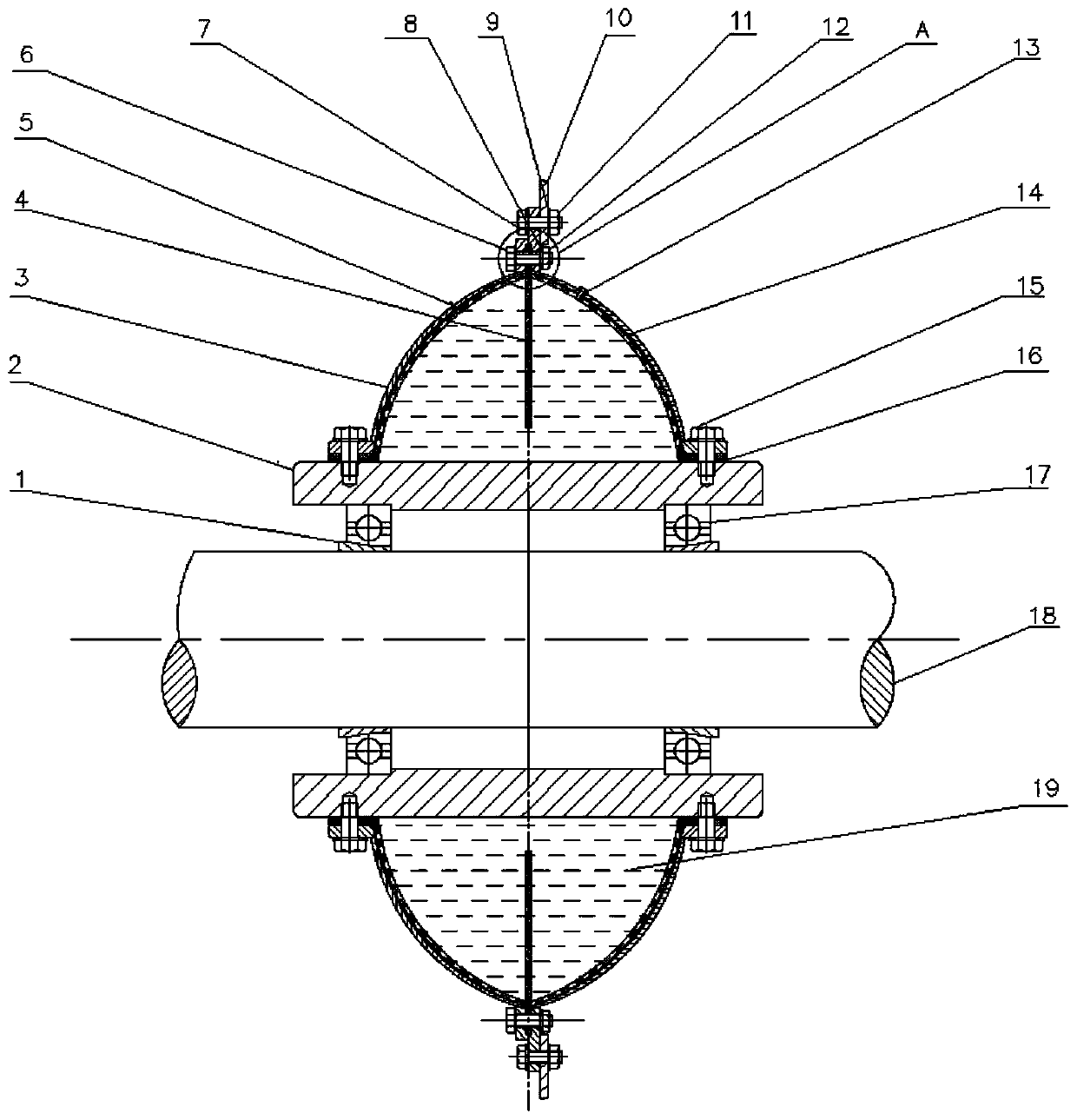
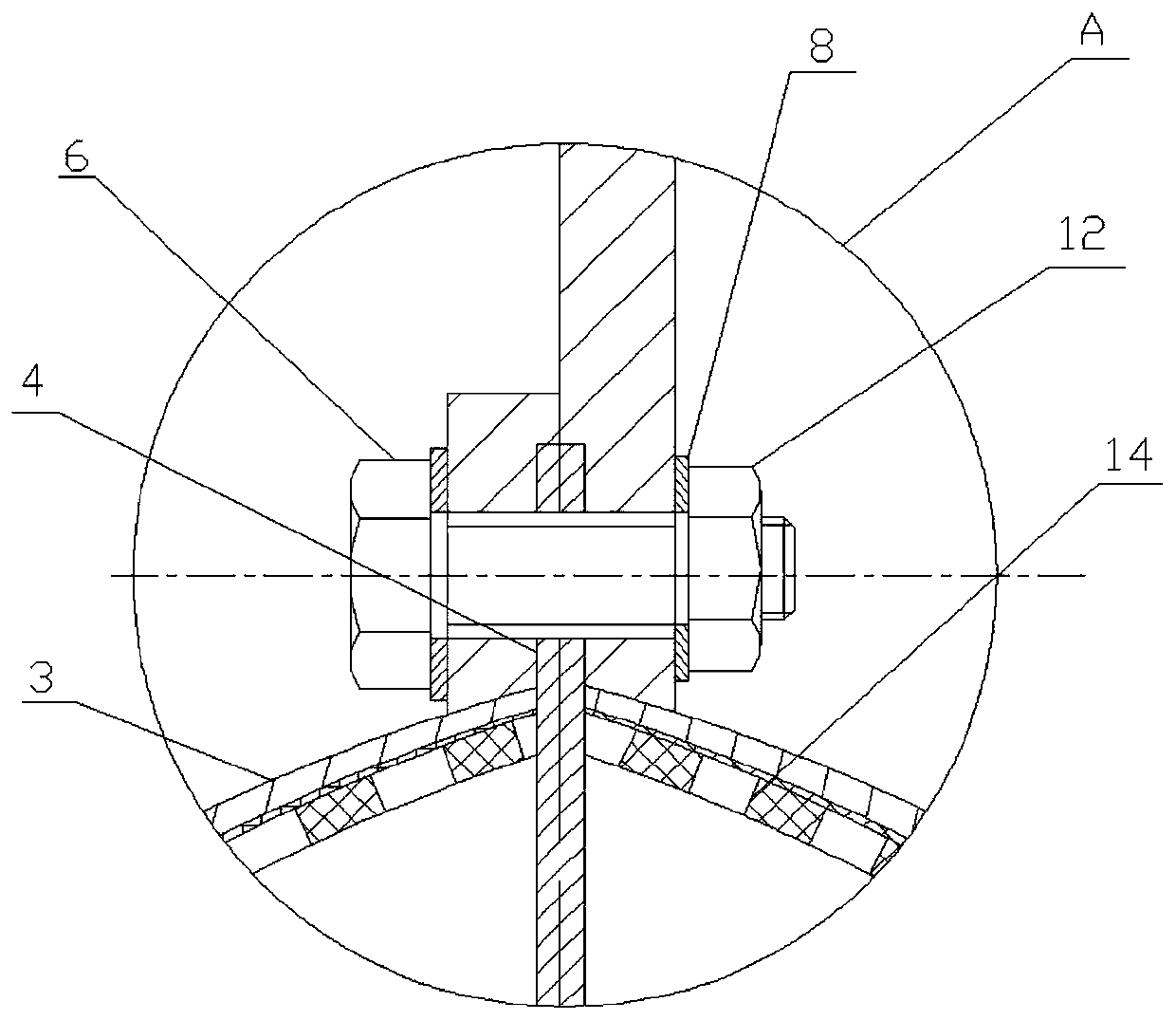
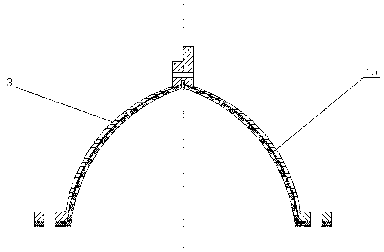
[0033] Such as Figure 1 to Figure 7 Shown: is a vibration damping device for ship shafting according to an embodiment of the present invention, including a shaft 18 and a bulkhead 10 supporting the shaft 18, and a pair of shaft sleeves with threads at the top are sleeved on the shaft 18 1. The bearing 17 whose inner mounting surface is a threaded taper is installed on the shaft sleeve 1, and the outer side of the bearing 17 ...


PUM


Abstract

The invention discloses a vibration damping device for a ship's shaft system, which includes a shaft and a bulkhead supporting the shaft, and two axially isolated shaft sleeves are fixedly fitted between the shaft and the bulkhead in sequence from the outer circle of the shaft to the outside. , 2 bearings, a cylindrical base body and a vibration damping cover, wherein the vibration damping cover is sealed and connected with the base body to form a sealed annular cavity body, and the cross section of the annular cavity body is The arc-shaped cone is provided with a flange at the top of the arc-shaped cone, and one end of the flange is fixed with a ring-shaped damping sheet with a number of through holes and extending into the annular cavity, and the other end It is fixedly connected with the bulkhead; the cover surface of the damping cover is provided with a refueling valve and an air release valve communicating with the annular cavity, and the annular cavity is filled with damping oil . The invention utilizes the combination of the damping sheet and the porous plate to achieve vibration reduction through the damping of the damping oil, has a simple structure, is convenient to disassemble, is suitable for different vibration working conditions by replacing the vibration damping sheet, and has a long service life.

Description

technical field [0001] The invention relates to a vibration damping device for ship shafting, in particular to a vibration damping base for ship shafting pulsation and a vibration damping method thereof, belonging to the technical field of ship shafting vibration reduction. Background technique [0002] Ship shafting vibration is one of the main sources of ship noise excitation, and excessive shafting vibration is one of the main reasons for shortening the life of ship power equipment. In the process of mechanical transmission, ship shafting is an important part of mechanical equipment. The engine of the ship will produce vibrations of different frequencies at different speeds, and the vibration will be transmitted to the hull structure through the shafting. Because the traditional shafting vibration reduction frequency band is narrow, it cannot effectively absorb vibration energy. Vibration has a great impact on the safety of ship equipment. The low-frequency vibration can...

Claims


Application Information

Patent Timeline
Patent Type & Authority Patents(China)
IPC IPC(8): F16F9/10B63H23/32
CPCB63H23/32F16F9/10F16F2222/12
Inventor 温华兵刘悦宋震洪良星靳玉冬
Owner JIANGSU UNIV OF SCI & TECH
Learn More