
DMD heat dissipation device

A heat dissipation device and heat technology, applied in the field of projection display, can solve the problems of increasing noise, reducing product reliability, and being unsuitable for small projection equipment, and achieving the effect of reducing noise and increasing product reliability.

Pending Publication Date: 2017-12-15
TECHNICAL INST OF PHYSICS & CHEMISTRY - CHINESE ACAD OF SCI
View PDF6 Cites 4 Cited by
  • Summary
  • Abstract
  • Description
  • Claims
  • Application Information

AI Technical Summary

Problems solved by technology

However, the use of fans for heat dissipation will increase the number of moving components, reduce product reliability, and increase noise. Water cooling requires a certain amount of space to install, so it is not suitable for small projection equipment, and water cooling also requires fans to dissipate heat.

Method used


Image

  • DMD heat dissipation device

Examples


Embodiment Construction

[0023] The present invention is described in detail by the following examples. It is necessary to point out that this example is only used to further illustrate the present invention, and can not be interpreted as limiting the protection scope of the present invention. Those skilled in the art can according to the above invention Some non-essential improvements and adjustments have been made to the content. In the case of no conflict, the embodiments and the features in the embodiments of the present invention can be combined with each other.

[0024] In addition, some orientation words mentioned in the embodiments of the present invention, such as "left", "right", "upper", "lower", etc., the meaning of these orientation words is related to the installation situation of the heat sink, not It should be understood as a limitation on the protection scope of the present invention.

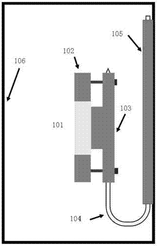
[0025] A DMD heat sink, such as figure 1 As shown, the device includes: a DMD fixing part 102; a ...


PUM


Abstract

The invention discloses a DMD heat dissipation device. The device comprises a DMD fixing piece, a first heat diffusion plate and a second heat diffusion plate, wherein the DMD fixing piece is attached to the back face of a DMD, and heat generated during work of the DMD is transmitted to the first heat diffusion plate; the second heat diffusion plate is connected with the first heat diffusion plate through a heat conduction device and attached to the inner side surface of a shell, so that the heat is further transferred to the shell for heat dissipation. The DMD heat dissipation device is suitable for small projection equipment with the optical power being dozens of watts. According to the DMD heat dissipation device, the heat generated during work of the DMD is transmitted to the shell through the first heat diffusion plate, the heat conduction device and the second heat diffusion plate, multi-stage heat dissipation is carried out, a fan is not needed, the noise is lowered, and the reliability of products is improved.

Description

technical field [0001] The invention relates to the technical field of projection display, in particular to a DMD cooling device. Background technique [0002] With the continuous improvement of projection technology, digital micromirror device (DMD) has been widely used. The principle is that white light is irradiated on DMD, and the reflection angle and time of tens of thousands of small mirrors on the chip are controlled to control The intensity of the pixel points of the screen can be used to obtain a grayscale image, and finally a color image can be obtained by superimposing the grayscale images of the three primary colors. [0003] However, when the white light is irradiated on the DMD, it will cause the temperature of the DMD to rise. At the same time, when the DMD is working, it will also generate heat, which will cause the temperature of the DMD to rise. Excessively high temperature will reduce the life of the DMD and even cause damage. Therefore, it is necessary t...

Claims


Application Information

Patent Timeline
IPC IPC(8): G03B21/16
CPCG03B21/16
Inventor 毕勇王栋栋张文平孙敏远高伟男房涛
Owner TECHNICAL INST OF PHYSICS & CHEMISTRY - CHINESE ACAD OF SCI
Learn More