
Anti-springback device of circuit breaker

An anti-bounce and circuit breaker technology, which is applied in the direction of emergency protection devices, circuits, and parts of protective switches, can solve problems such as ineffective anti-bounce devices, small electric repulsion, and device failure, so as to protect against burnout and reduce Rebound effect, simple structure effect

Active Publication Date: 2017-12-15
SHANGHAI RENMIN ELECTRICAL APP WORKS
View PDF5 Cites 2 Cited by
  • Summary
  • Abstract
  • Description
  • Claims
  • Application Information

AI Technical Summary

Problems solved by technology

This known anti-bounce device can sometimes play the role of anti-bounce when short-circuiting large currents, but the reliability is not high; it can hardly work when short-circuiting small currents
The main reasons are as follows: Compared with the tension and compression spring, the error of the reset torsion spring is not easy to control. If the parameter of the torsion spring is too large, the locking part will not swing downward enough. Before the gear collides with the stop gear, the device will fail; the current value of the circuit breaker to break the short-circuit current is different, the short-circuit current is large, the electric repulsion is large, and the opening speed is fast, the short-circuit current is small, the electric repulsion is small, Therefore, the opening speed is slow. Under different opening speeds, the downward swing of the locking member is different, so this kind of anti-bounce device will not work at certain opening speeds.
In addition, this kind of anti-bounce device is fixed on the transmission part that rotates with the main shaft, which will inevitably affect the opening and closing speed of the circuit breaker.

Method used


Image

  • Anti-springback device of circuit breaker
  • Anti-springback device of circuit breaker

Examples


Embodiment

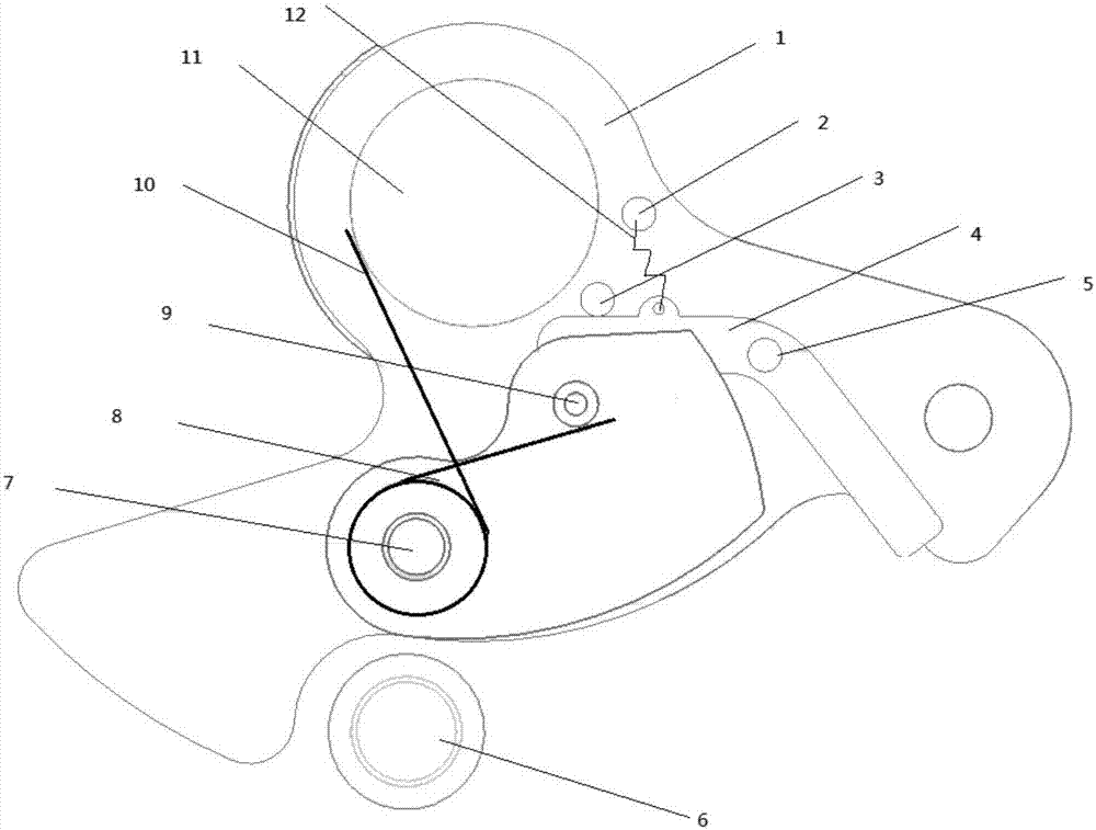
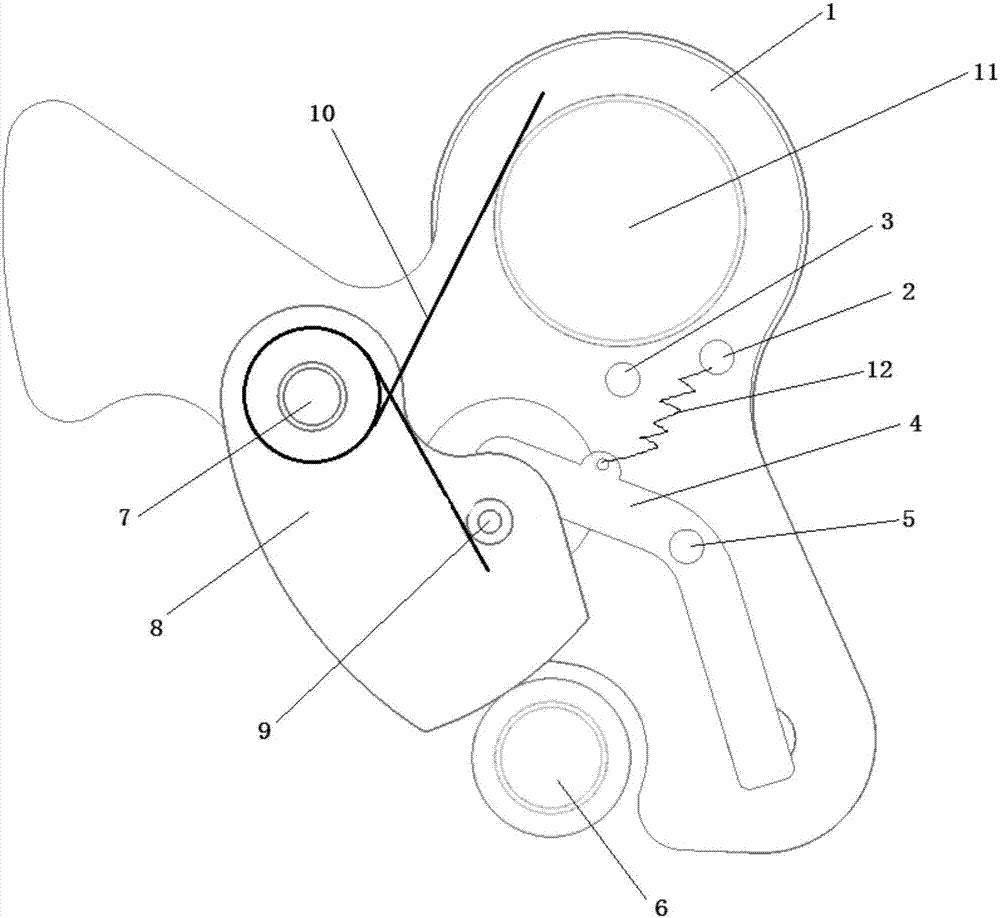
[0024] An anti-rebound device for a circuit breaker, the circuit breaker includes a main shaft 11, a cantilever 1 welded on the main shaft 11, and a limit rod a6 arranged under the main shaft to limit the rotation position of the cantilever. The cantilever 1 includes a head and two The side wings with hooks, the head is welded on the main shaft 11, the limit rod a6 is arranged between the two side wings, and the rotation range of the cantilever 1 is limited by contacting with the hooks. The cantilever 1 is provided with a fixed rod 2, a limiting rod b3, a rotating shaft a5, a rotating shaft b7 and a limiting hole. The anti-rebound device includes a booster plate 4 and a hanging plate 8, and one end of the hanging plate 8 is installed on the rotating shaft b7 , the middle part of the hanging plate 8 is provided with a limit rod c9, the limit rod c9 can move in the limit hole, the booster plate 4 is installed on the rotating shaft a5, the booster plate is a bent plate, including ...


PUM


Abstract

The invention relates to an anti-springback device of a circuit breaker. The anti-springback device comprises a main shaft (11), a cantilever (1) welded on the main shaft (11), a limiting rod a (6) arranged below the main shaft for limiting a rotational position of the cantilever, a hanging plate (8) connected with the cantilever (1) by means of a rotating shaft b (7), and an assistance plate (4), wherein the assistance plate (4) is a bent plate and comprises a side plate a and the side plate b, and the assistance plate (4) is connected with the cantilever (1) by means of a rotating shaft a (5); in an initial state, the side plate a is located in front of the side wing of the cantilever (1); and in a switching-off state, one end of the hanging plate (8) is connected with the cantilever (1), and the other end of the hanging plate (8) is tangent to and compresses the limiting rod a (6). Compared with the prior art, the anti-springback device of the circuit breaker makes the anti-springback function more obvious, and plays the role of preventing springback and reducing springback, so that the springback of a moving contact in the switching-off process is reduced to prevent re-striking of electric arcs, thereby protecting the entire circuit against burning down.

Description

technical field [0001] The invention relates to the technical field of low-voltage electrical appliances, in particular to an anti-rebound device of a circuit breaker. Background technique [0002] Since the speed of the circuit breaker opening is very fast, and the circuit breaker mechanism is made of rigid materials, the bouncing phenomenon is serious when the circuit breaker is opening. After the moving and static contacts of the circuit breaker reach the maximum opening distance, there will be a large rebound, and the rebound range can reach half of the opening distance, and even the moving and static contacts will re-contact. This kind of bouncing will cause the arc to not be extinguished in time. Even the arc reignites, causing the moving contacts and static contacts to burn out, and even more serious consequences. Therefore, it has always been a key research issue in the low-voltage electrical industry to solve the excessive rebound distance of the moving contact dur...

Claims


Application Information

Patent Timeline
Patent Type & Authority Applications(China)
IPC IPC(8): H01H71/10
CPCH01H71/504H01H71/10
Inventor 舒少龙徐琛君范琨
Owner SHANGHAI RENMIN ELECTRICAL APP WORKS
Learn More